This is part three in a five-part series on airframe structures and control surfaces. This tutorial focuses on the structural design of an aircraft wing and introduces the various control surfaces attached to the wing’s trailing edge.
Introduction
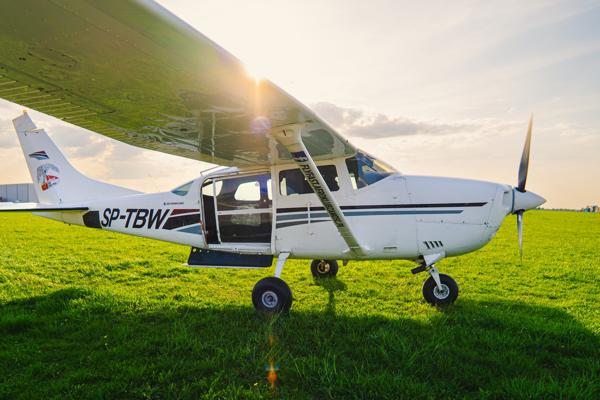
A wing is designed to produce sufficient lift to support the aircraft throughout its design envelope. Every wing is therefore designed to produce and support a multiple of the total weight of the airplane. This is termed the load factor and was discussed in part one of this series. Most general aviation aircraft are designed to a load factor of between four and six. The various components that make up the wing structure must be capable of supporting this aerodynamic load throughout the certified design envelope.
Wing Loads
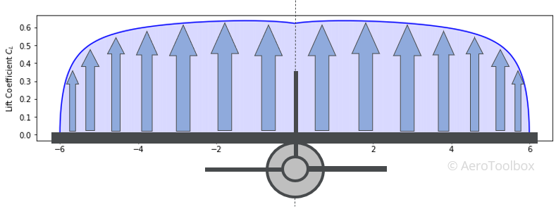
A wing is not designed to produce an equal upward force at all points along the span but rather produces the greatest percentage of the total lift closer to the root, diminishing outwards towards the span.
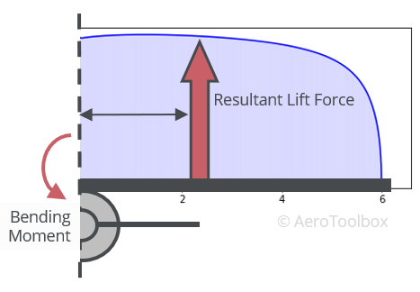
The maximum wing loads are seen at the wing root where the wing attaches to the fuselage. The two primary contributors to the total stress are the vertical lift force and the resulting bending moment. The wing also tends to pitch up and down during flight which is reacted at the root by a torque at the attachment points.
Induced drag is formed as a by-product of the lift generated, and along with profile drag introduce forces into the wing which tend to push the wing backward. While the magnitude of the drag force produced is a lot smaller than the lift, the structure must still be designed to support these forces at the limits of the design envelope.
Wing Layout
Wing Configurations
There are many different wing configurations in use today. We can broadly classify a wing-fuselage interface in terms of three design variables: the number of wings used to produce the required lift, the location of the wing, and the wing-fuselage attachment methodology.
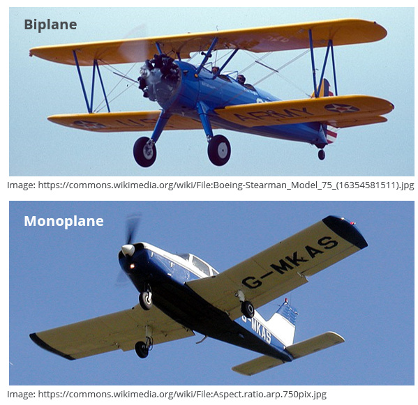
Number of Wings
A triplane has three wings, a biplane two, and a monoplane the most common configuration in use today, has a single primary lifting surface.
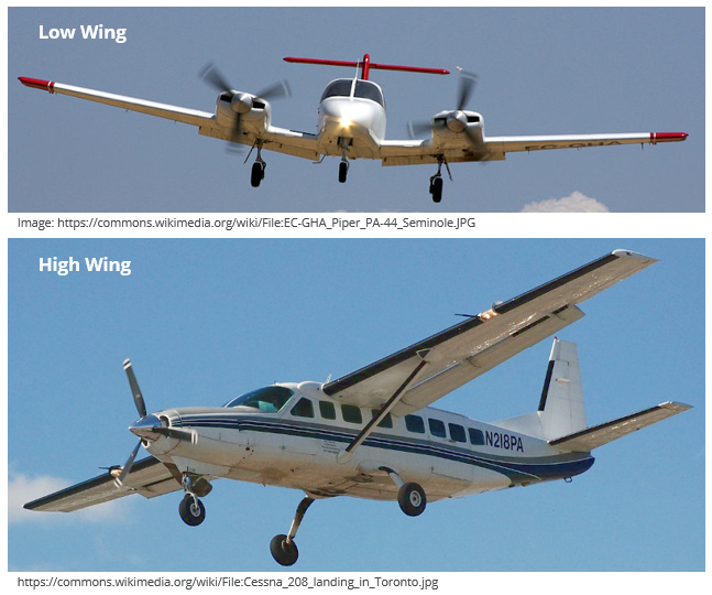
Wing Location
Wings can be located above the fuselage (high wing), through the center of the fuselage (mid wing), or towards the bottom of the fuselage (low wing).
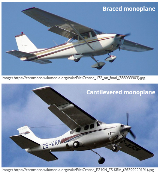
Cantilevered or Braced
A cantilevered wing has no external bracing and is connected to the fuselage only at the root. Many light aircraft make use of a strut which reduces the bending moment at the wing root, allowing a smaller (lighter) wing-to-fuselage attachment. The strut may reduce the bending at the root but does produce more drag than an equivalent cantilevered wing.
Design Considerations
Designing the planform or shape of a wing is a complicated process undertaken to optimize the aircraft for a particular mission. In our Fundamentals of Aircraft Design series there are three posts dedicated to preliminary wing design. You are encouraged to go and read through the posts on wing area and aspect ratio, sweep and airfoil aerodynamics if you are interested.
Here we will briefly touch on two wing design variables: the planform wing area and the aspect ratio, which are two primary drivers behind the performance of a general aviation wing.
The wing area is defined as the planform surface area of the wing. This is the area of the wing when viewed from directly above the aircraft.
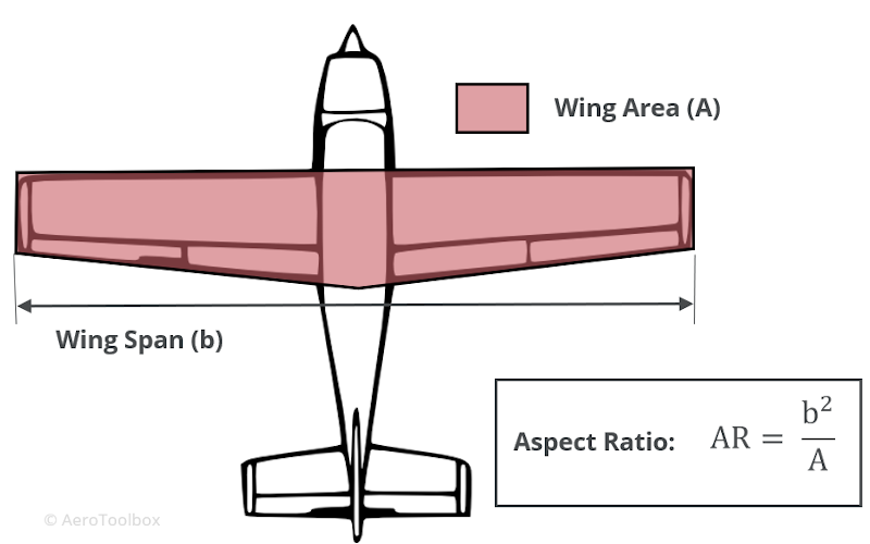
The aspect ratio is the ratio of the span of the wing to its chord. There are very few perfectly rectangular wings and so a little manipulation is required in order to calculate the aspect ratio of a tapered wing.
$$ AR = \frac{b^2}{A} $$
Wing Area
Lift is an aerodynamic force which is produced as a consequence of the curvature of the wing and the angle of attack of the relative velocity flowing over the surface. It follows that larger wings of a greater planform area are able to produce more lift; this is easily shown mathematically from the lift formula:
$$ L = \frac{1}{2} \rho V^{2} A C_{L} $$
Where:
\( L: \) Total Lift Force
\( \rho: \) Air density
\( V: \) Velocity
\( A \) Planform Wing Area
\( C_{L}: \) Lift Coefficient
The total lift force is increased in proportion with the wing area.
A better gauge of the relative size of the wing is the wing loading which is calculated by dividing the aircraft mass by the wing area.
$$ WL = \frac{Weight}{Wing \ Area} $$
If we assume that the aircraft is flying at a 1g load factor then the lift will be equal to the weight and the lift formula can be rearranged in terms of velocity. The effect that wing loading has on cruise speed can be shown by comparing two general aviation aircraft with two very different wing loadings: the Cessna 172 and the Lancair Legacy.
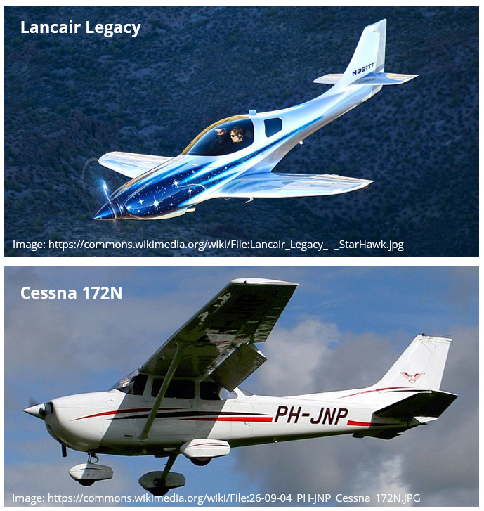
| Cessna 172 | Lancair Legacy | Ratio: Legacy/172 | ||
|---|---|---|---|---|
| Gross Weight | 1111 | 998 | kg | |
| Wing Area | 16.2 | 7.66 | m² | 0.47 |
| Wing Loading | 68.6 | 130.3 | kg/m² | 1.90 |
| Cruise Speed | 122 | 240 | knots | 1.96 |
| Stall Speed | 47 | 56 | knots | 1.19 |
$$ V_{cruise} = \frac{2 WL}{\rho C_{L_{cruise}}} $$
The lift formula is rearranged to determine speed as a function of wing loading and the lift coefficient. If we assume that the lift coefficient is approximately constant between the two aircraft during cruise (this is an acceptable assumption here to demonstrate the concept of wing loading), then we can compare the effect that wing loading has on the resulting cruise speed.
An increased wing loading corresponds to a smaller wing at a given mass, and results in an increased cruise speed. Of course the Legacy has a much larger engine which allows it to reach a far higher cruise speed (drag is proportional to V^2), but the point still stands that an aircraft that is designed to cruise at higher speeds will do so most efficiently with a higher wing loading. The highly loaded wing also results in a higher stall speed (clean), and a more complicated flap arrangement (greater increase in lift coefficient) is thus required to reduce the stall speed.
Aspect Ratio
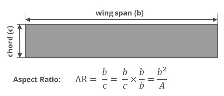
The aspect ratio was introduced in the section above and is a measure of the shape of the wing. On a rectangular wing it is determined by the ratio of the span to chord. On a tapered wing it can be found using the formula:
$$ AR = \frac{b^2}{A} $$
High aspect ratio wings are long and thin while low aspect ratio wings are short and stubby. The aspect ratio plays an important role in determining the amount of lift-induced drag generated.
$$ C_{D_{i}} = \frac{C_{L}^{2}}{\pi AR e} $$
\( C_{D_{i}}: \) Lift-induced Drag Coefficient
\( C_{L}: \) Lift Coefficient
\( AR \) Wing Aspect Ratio
\( e: \) Oswald Efficiency Factor
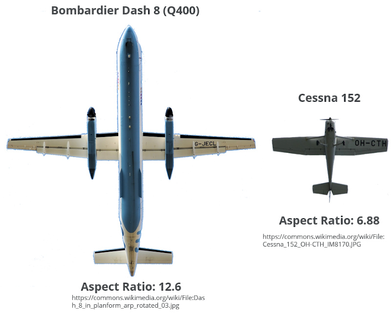
Higher aspect ratio wings result in a lower lift-induced drag coefficient. This is why gliders have long slender wings (high AR) as drag minimization is paramount to obtain the best glide ratio. A high aspect ratio wing is more structurally challenging to design, as the wing will flex more in flight, creating larger bending stresses and a damped roll control response. Structural flutter is also more prevalent in higher aspect ratio wings.
Control Surfaces
Flaps and ailerons are located at the trailing edge of the wing. Both control surfaces work by modifying the local camber and lift distribution over the area in which they operate. Ailerons are used for roll control and are located at the outboard section of each wing. Flaps are located inboard of the ailerons and are used to generated additional lift at low speeds through symmetrical deployment.
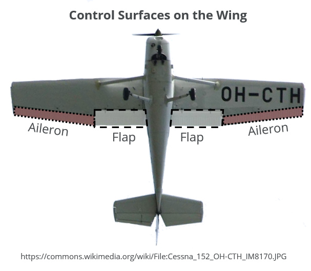
The flaps and ailerons are attached to a rear spar which runs along the span. The spar is designed to resist and transfer the loads generated by the deflection of the control surfaces.
Trailing edge flaps are one of two devices used to extract additional lift from a wing at low speed. Slats modify the camber at the leading edge, performing a similar roll to the flaps. High-lift devices are a large topic on their own and are discussed in detail in Part 4 of this mini-series.
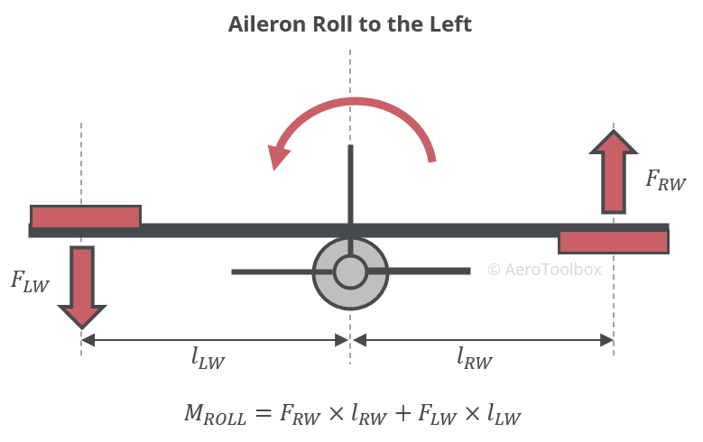
Ailerons are used to provide roll control and do so by generating a large rolling moment through asymmetrical deflection. The figure below demonstrates a roll to the left. The aileron on the right wing deflects downwards which produces additional upward lift on the right wing. The left aileron deflects upward which modifies the flow field, generating a downforce at the left wingtip. Together these deflections generate a rolling moment which forces the right wing up, and the left wing down.
Semi-monocoque Wing
The various structural design methodologies were discussed in part one of this series. This discussion on the structural design of a wing only considers the semi-monocoque design philosophy as it is the most popular structural layout in use today.
In a semi-monocoque structure both the outer skin and the internal substructure are load bearing, and both contribute to the overall stiffness of the structure. A semi-monocoque structure is well suited to being built from aluminium as the material is both light and strong. The density of an aluminium alloy is approximately one-third that of steel which allows for thicker structural sections to be built from aluminium than would be possible with a steel structure of equivalent mass. Thicker skins are advantageous as these are less likely to buckle under load. This allows for an efficient structure to be constructed as the wing skins can be used to distribute and carry the loads generated by the wing.
Structural Components
A typical wing internal structural layout is shown in the image below:
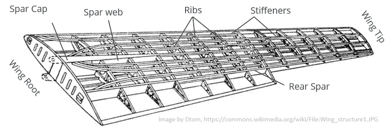
A wing is comprised of four principle structural components that work together to support and distribute the aerodynamic forces produced during flight.
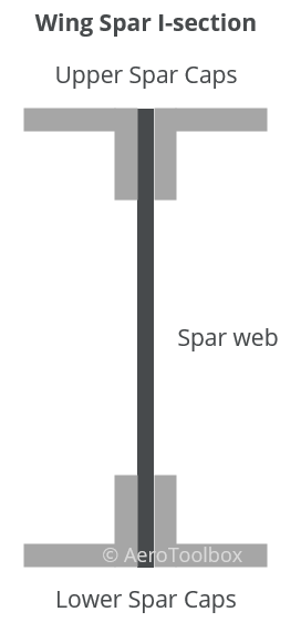
Wing Spars
These make up the longitudinal components of the structure. A spar is made up of two components: the spar web and the spar caps. The two components typically are arranged to form an I-section.
The spar caps are designed to the carry axial loads (tension and compression) that arise from the bending moment produced by the wing under load. In a positive g manoeuvre, the spar caps on the upper surface of the wing are in compression and the lower spar caps surface in tension.
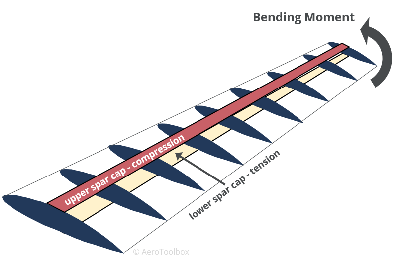
The cross-sectional areas of the spar caps determine how much load each can support. Since the bending moment is greatest at the root of the wing and smallest at the tip, it is common for the spar caps to be tapered from root to tip in order to minimize the structural mass of the wing.
The spar web separates the upper and lower spar caps and carries the vertical shear load that the wing produces. The web also adds torsional stiffness to the wing and feeds load into the spar caps through shear flow.
Stiffeners
These are longitudinal components that perform a similar function to the spar caps in that they carry axial loads that arise from the bending of the wing. The stiffeners are spaced laterally through the wing to support the wing skins against buckling.
Ribs
Wing ribs are spaced along the span of the wing and give the wing its aerodynamic shape. The ribs, spar caps, and stiffeners form bays throughout the wing that support the wing skins against buckling. Any point loads introduced into the wing are done so at ribs which form hardpoints. Landing gear legs and engine mounts are supported by especially sturdy ribs, as the loads introduced by these components can be very large.
Skins
The wing skins is a semi-monocoque structure are load bearing and carry and transmit shear loads into the neighbouring spar caps and stiffeners.
This concludes this post on the wing structural layout. The next post provides a more detailed look at the design and operation of a typical high-lift system.
If you enjoyed this post or found it useful as a study aid, then please introduce your colleagues and friends to AeroToolbox.com and share this on your favorite social media platform. Thanks for reading.


