
Introduction
This is part 8 in the Fundamentals of Aircraft Design series. In the previous posts we’ve looked at both the wing and fuselage in some detail. Now we move onto the aircraft tail section and examine the function of both the horizontal and vertical tail. We'll then introduce an empirical method to size both surfaces on a new aircraft design.
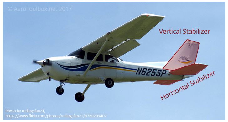
Almost all aircraft flying today have a tail located towards the rear of the fuselage. While there are a number of possible tail configurations, the majority are comprised of a horizontal surface and a vertical surface which stabilize the aircraft in the longitudinal and directional axis respectively.
The two tail surfaces are shown below in a conventional layout pictured on a Cessna 172.
The Tail Assembly
The tail assembly (horizontal and vertical stabilizer) is also known as the empennage which originates from the French term empenner which means to “feather an arrow”. Similar to how the feathers on an arrow stabilize the arrow in flight, the tail ensures that the aircraft remains stable through all phases of operation.
An aircraft tail has two primary objectives:
- To provide stability in the longitudinal (pitch) and directional (yaw) axes during flight.
- To assist in the pitch and yaw control of the aircraft by the movement of control surfaces affixed to the stabilizing surfaces.
Classification of Aircraft Tails
There are a number of common empennage arrangements that most aircraft adhere to. Some of the most common configurations are shown below.
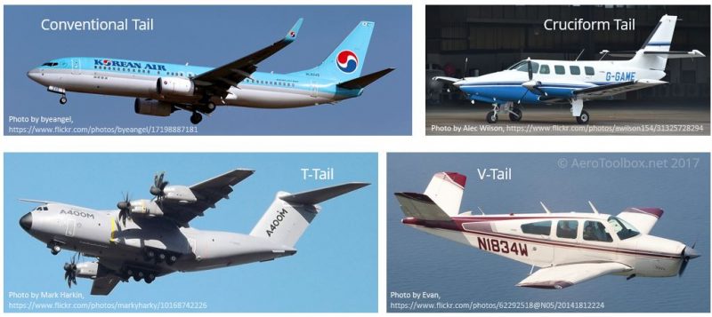
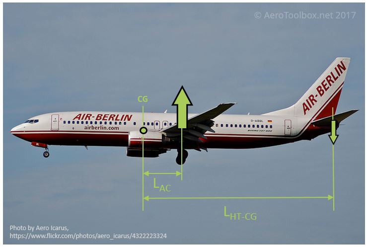
As the name suggests, the conventional tail arrangement is the most common. In this configuration, the vertical tail sits at the rear of the fuselage with the horizontal stabilizer attached to the fuselage below the vertical tail. This arrangement works well when the aircraft engines are placed under the wing (as shown on the B737-800) where the hot engine exhaust may be kept well away from the horizontal stabilizer. This is a structurally efficient arrangement as the horizontal stabilizer is fixed directly to the fuselage and therefore can introduce and distribute the resulting load directly into the fuselage structure.
Aircraft that have a high wing (such as the A400M pictured above) often make use of a T-tail arrangement where the horizontal stabilizer is attached to the top of the vertical stabilizer. Often the primary reason to make use of this arrangement is to prevent the horizontal tail from being blanketed by the wake generated by the wing at high angles of attack. A high wing and conventional tail arrangement is especially susceptible to this phenomenon. T-tails are also often used when engines are mounted to the rear of the fuselage as often seen on business jets. This is to keep the hot engine exhaust away from the tail surfaces. One advantage of the T-tail arrangement is that the horizontal tail acts as an end-plate for the vertical tail. This makes the vertical tail more aerodynamically efficient which means it can be reduced in size. However, mounting the horizontal stabilizer on top of the vertical tail necessitates that the tail structure be much stronger (heavier) to accommodate the load introduction of the horizontal tail directly into the vertical tail.
Somewhere between the two configurations discussed above is the cruciform tail arrangement. Here the horizontal tail is placed near the midpoint of the vertical tail. The Cessna T303 shown as the example for the cruciform arrangement was most probably was designed with a cruciform to reduce the flow of propeller wake over the horizontal tail, which may cause buffering during flight.
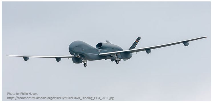
A few aircraft, like the Model 35 Beech Bonanza, have been designed with a V-tail arrangement where the three conventional surfaces (vertical tail, port (L) and starboard (R) horizontal tail sections) are replaced with two surfaces placed in a V formation. The horizontal and vertical components of the surfaces act as a horizontal and vertical stabilizer respectively. The V-tailed Bonanza was produced between 1947 and 1982 before being phased out in favor of the conventional tailed Model 33 and 36. A more recently designed V-tailed aircraft is the Northrop Grumman RQ-4 Global Hawk unmanned aerial vehicle which first flew in 1998.
Horizontal Stabilizer
To understand why a conventional aircraft requires a horizontal stabilizer one only needs to plot the force vectors acting on the aircraft during flight. An aircraft with the horizontal stabilizer at the rear of the fuselage will always be designed such that the center of gravity (c.g.) sits ahead of the wing’s center of lift. The wing therefore imparts a nose-down pitching moment on the aircraft, the magnitude of which is the resulting lift force multiplied by the moment arm between the center of lift and the c.g. This is a deliberate design as it means that any time the aircraft’s nose pitches up, the wing will provide a restorative moment that will tend to bring the nose back down. This is termed longitudinal static stability and is the hallmark of a safe and stable airplane.
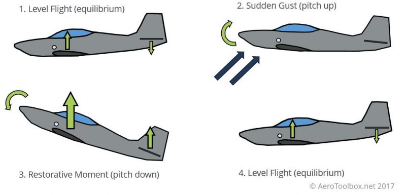
In order to balance this pitch-down moment generated by the wing in level flight, a moment of equal magnitude but opposite direction must be generated to keep the aircraft in balance. This moment is generated by the horizontal tail and is equal to the magnitude of the normal force generated by the stabilizer multiplied by the distance between the c.g. and the center of pressure (downforce) of the horizontal stabilizer. A convention arrangement with the tail to the rear of the aircraft will necessitate that the aerodynamic force generated by the horizontal stabilizer be downward in level flight.
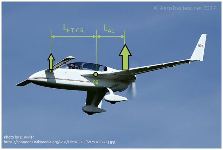
Another horizontal stabilizer configuration sometimes seen is the Canard configuration. Here the horizontal stabilizer is placed ahead of the wing rather than behind. This configuration works in much the same manner as the conventional layout except that the balancing force generated by the horizontal stabilizer (canard) is upward rather than downward. In this configuration the centre of gravity is still ahead of the centre of lift of the wing and as such the aircraft remains statically stable in the longitudinal axis.
Finally, it is worth pointing out that a horizontal stabilizer is not always a prerequisite to produce a stable aircraft. Flying-wings like the Northrop Grumman B-2 Spirit are designed with a reflexed airfoil which allow the aircraft to remain statically stable without a horizontal stabilizer provided the aerodynamic center of the wing is behind the c.g.
Vertical Stabilizer
Similar to the way that the horizontal stabilizer controls the longitudinal stability of an aircraft, the vertical stabilizer is designed to control stability in the directional or yaw axis. Generally the vertical stabilizer points upward and works in the same manner as the rear fin on a weather vane. An example of the contribution of the vertical stabilizer to yaw stability is shown below:
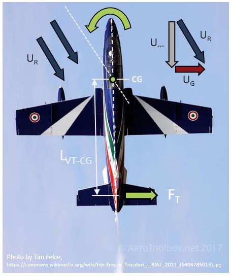
Suppose an aircraft is flying and a gust of magnitude \(U_{G}\) hits the aircraft from the left hand size. The gust causes the local velocity over the vertical tail to be such that the tail is effectively inclined at an angle of attack to the relative wind (\(U_{R}\)). This causes a lifting force (\(F_{T}\)) to be generated such that a moment \(F_{T} \times L_{VT}\) will yaw the aircraft into the direction of the relative wind. This is a stable situation, much like a weathervane, the aircraft will always tend to point into the direction of the relative wind. If the vertical stabilizer was placed ahead of the center of gravity it would have a destabilizing effect and tend to push the aircraft away from the relative wind.
Control Surfaces
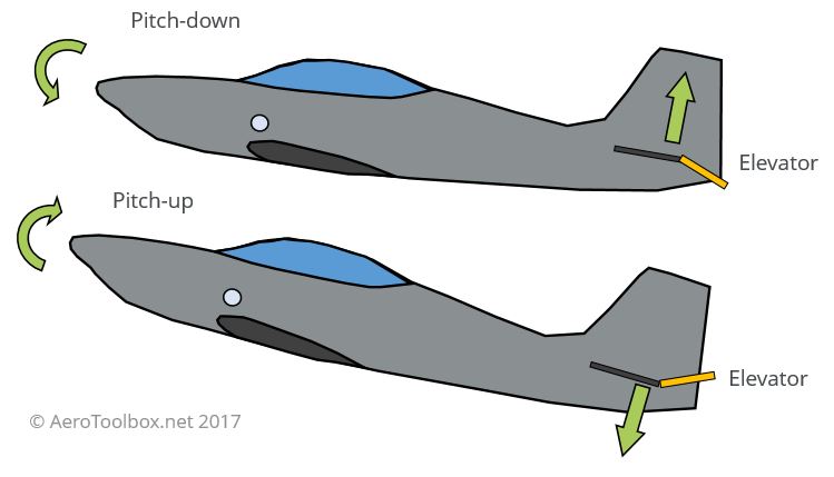
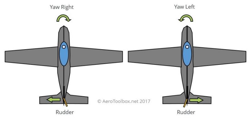
Stabilizing the aircraft in flight is one of the two primary objectives of the vertical and horizontal stabilizer. The second is to provide a platform from which to control and manipulate the movement of the aircraft through the air. Both stabilizers are fitted with a primary control surface; an elevator to control pitch on the horizontal stabilizer, and a rudder to control yaw on the vertical tail. In some cases the entire horizontal stabilizer rotates to provide a control function. This is termed an all moving tail.
Both the primary control surfaces and smaller secondary trim tabs are visible in the image below. Trim tabs allow the pilot to fix the control position such that the aircraft will remain in a fixed aerodynamic configuration with the pilot’s hands off the control column.
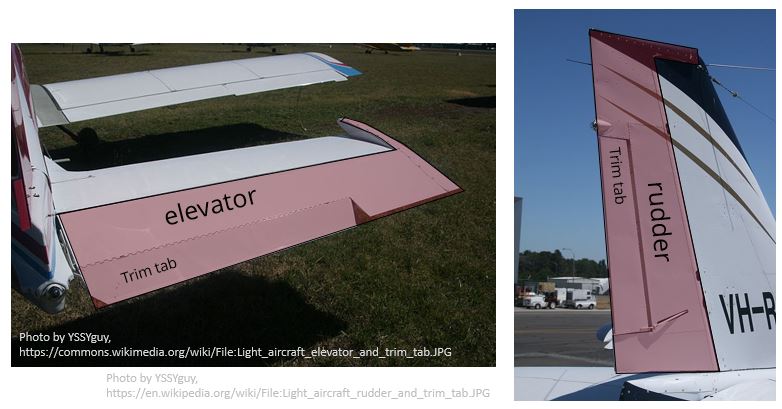
The elevator and rudder are both movable surfaces fixed to the trailing edge of the horizontal and vertical stabilizer respectively. Deflecting the control surface modifies the camber of the surface which induces a force normal to the direction of flight and causes, the aircraft to rotate about the center of gravity either in pitch (elevator) or yaw (rudder).
Sizing the Stabilizer Surfaces
Sizing the vertical and horizontal tail is an iterative process that during the preliminary stages of design, is largely empirical. A good starting point is to first study existing aircraft of similar size and configuration, and to use this as a basis for sizing your design. The primary design function of both stabilizing surfaces is to provide stability in their respective axes and so initially sizing surfaces according to what is currently flying should provide you with a good first approximation of the size required. Remember that the larger the final stabilizing surface, the greater that surface’s contribution to the overall aircraft drag, and so the tail should be sized as small as possible but sufficiently large so as to ensure that all stability criteria are met.
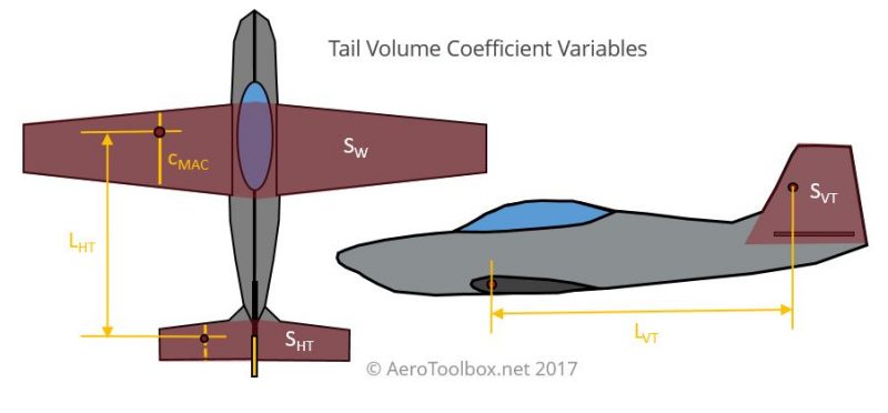
One popular method in the preliminary sizing of stabilizing surfaces is to make use of non-dimensional volume ratios which relate the size of the wing and length of the aircraft to the required horizontal and vertical tail area. Remember to always use a consistent set of dimensions when calculating the ratios (m & m2 or ft & ft2).
$$ C_{HT} = \frac{S_{HT}\cdot L_{HT}}{S_{W} \cdot c_{MAC}} $$
$$ C_{VT} = \frac{S_{VT}\cdot L_{VT}}{S_{W} \cdot b} $$
Where:
\(S_{W}\) = Wing Area
\(c_{MAC}\) = Mean Aerodynamic Chord
\(b\) = wing span
\(S_{HT}\) = Horizontal Tail Area
\(S_{VT}\) = Vertical Tail Area
\(L_{HT}\) = Length between the aerodynamic centers of the wing and horizontal tailplane
\(L_{VT}\) = Length between the aerodynamic centers of the wing and vertical tailplane
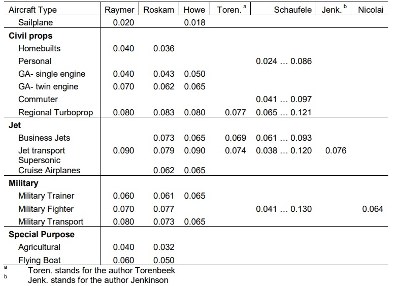
Different aircraft types have different target volume ratios and some examples of aircraft types and corresponding target volume ratios are shown below. The two tables below have been really nicely put together and formatted by Priyanka Barua, Tahir Sousa & Dieter Scholz in a Technical Note entitled Empennage Statistics and Sizing Methods for Dorsal Fins written at the Hamburg University of Applied Sciences. The table have been reproduced verbatim and interested readers are encouraged to view the full paper which is available to download here.
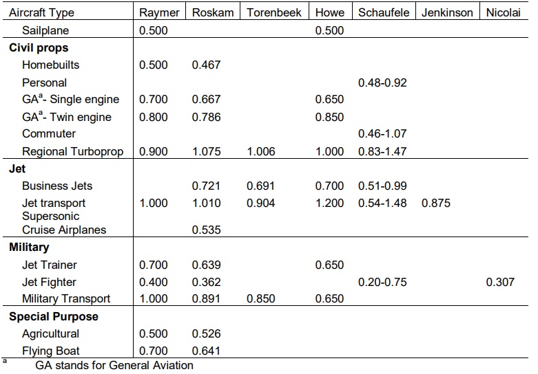
Using the tail volume coefficients given above, the horizontal and vertical tail area can be estimated. Once the stabilizer area is know, the planform can be sketched out after selecting an aspect and taper ratio (the Wing Plot Tool on this website is a useful way to visualize what the surface will look like).
The following are some general rules of thumb that may prove useful when specifying the horizontal and vertical tail planform area:
- A symmetrical airfoil profile should always be used for both the horizontal and vertical stabilizer as the net force acting on both will change direction during the course of flight depending on which direction the elevator or rudder is deflected. Two common profiles to consider using is the NACA 0010 or NACA 0012 airfoil (download the airfoil coordinates using the NACA 4 Series Plot Tool).
- The aspect ratio of the horizontal tail should always be less than the aspect ratio of the wing. Lower aspect ratio wings stall at higher angles of attack and so it follows that the horizontal stabilizer should have a lower aspect ratio so that control authority is still available after the wing has stalled.
- A typical aspect ratio for a vertical tail is in the range of 1.3 to 2.0 (here the aspect ratio is based on the span from root-to-tip as the span from tip-to-tip has no meaning in the case of a vertical stabilizer).
The empirical method outlined above is useful as a first approximation as to the size and shape of the stabilizers required. This would typically form the input to a more detailed analysis of the surfaces including sizing of the elevator, rudder, and associated trim tabs as well as a detailed study into the stability characteristics of the aircraft. Both a static and dynamic stability analysis would need to be undertaken and would include such calculations as:
- Longitudinal static stability (will the aircraft return to a neutral state after an upward or downward gust).
- Directional static stability (will the aircraft return to a neutral state after a cross-wind gust).
- VMCA calculation (is the aircraft able to maintain directional control with one engine inoperative at a speed close to stall).
- Longitudinal and Lateral trim calculation (is the aircraft able to remain in trim for a variety of speeds and altitudes).
- Spin recovery
- Tail stall
- Deep stall
- Handling quality tests
- Horizontal stabilizer incidence
As you can see from the list of calculations given above there is a lot of analysis that goes into the sizing of the horizontal and vertical tail. What has been written above forms a basic introduction to the empennage surfaces present on an aircraft and should hopefully provide you with a starting point for how to go about the design of a tail for a new aircraft.


