This is Part 7 of a series on the Fundamentals of Aircraft Design. In part 6 we looked at the structural make-up of the wing. In this post, we move away from the wing and introduce aircraft fuselage design: we’ll look at the various ways to construct a fuselage, how to size it correctly, and introduce the various loads that the fuselage structure is expected to carry during operation.
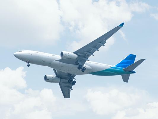
The main body section of an aircraft is called a fuselage. This forms the central body of the aircraft onto which wings, control surfaces and sometimes engines are connected. The fuselage houses the crew, any passengers, cargo, an array of aircraft systems and sometimes fuel.
A well designed fuselage will ensure that the following are met:
- The intended payload is adequately and efficiently housed.
- The fuselage is sized such that the various control and stabilization surfaces (typically the vertical and horizontal tail) are located such that the aircraft is stable in flight.
- Loading the aircraft with goods, fuel and passengers does not negatively impact on the stability of the aircraft for a range of payload configurations (center of gravity is adequately located).
- The fuselage structure will not fail due to excessive loading throughout the entire aircraft flight envelope.
- The mass of the fuselage is optimized to ensure safe operation without carrying any additional or excess weight.
- The aerodynamic shape of the fuselage is such that the minimum drag is produced during typical operation while still ensuring that the design payload is adequately housed.
- The fuselage design is versatile enough to offer the potential to stretch the aircraft if a number of aircraft configurations are desired.
Let’s start by examining three popular design methodologies for the structural design of a fuselage.
Structural Design Principles
Throughout the years a number of design principles have been adopted regarding the structural layout of a fuselage. Three common design methodologies are described below in chronological order leading up to the semi-monocoque design that is most prevalent today.
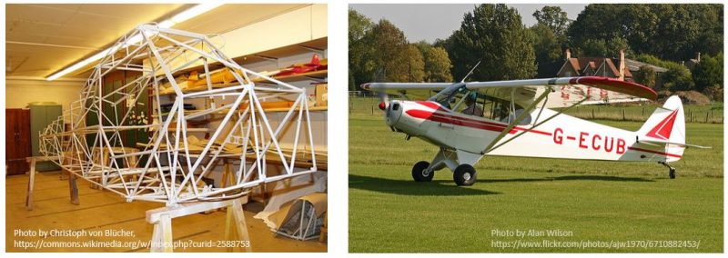
Space Frame (Truss)
The earliest aircraft fuselages were built with a space frame or truss like construction. Often wood was used as the primary structural material with a fabric covering providing the aerodynamic shape. In this fuselage configuration the force members of the truss provide the structural stiffness, and the aerodynamic covering provides the shape, but does not add much to the overall stiffness of the structure. A space frame is a simple albeit inefficient way of building a fuselage structure as the fabric skins add weight without contributing to the rigidity of the structure. One popular aircraft designed with a space frame fuselage is the iconic PA-18 Piper Super Cub which is pictured below.
Monocoque
By the end of the First World War limitations in the the use of wooden truss configurations were being identified. As the flight speed and wing loading of newer designs increased, the variation of the structural properties of the wood and its susceptibility to environmental degradation meant that wooden structures were no longer an efficient means of production. New methods were sought and steel was investigated as a replacement for wood. Steel is stiff and strong (both prerequisites in the design of an efficient structure) but its high density makes it very heavy (density of wood approximately 500 - 800 \( kg/m^3 \) vs steel 7800 \( kg/m^3 \)). To efficiently design with steel, engineers had to make use of very thin sections which were intricately curved and shaped to prevent buckling of the thin structure. The term monocoque structure refers to a structural arrangement where the skins take all of the loading and contribute to all of the structural rigidity of the design. One major downfall when designing a pure monocoque structure is the difficulty of incorporating concentrated loads into the structure such as engine mountings or the wing-fuselage interface. The distribution of these point loads into the skin structure becomes very difficult to efficiently achieve. Interestingly, in recent times the introduction of composites as a material from which to build aircraft structures has seen a move back towards designing a pure monocoque structure, although typically a hybrid design of a metallic substructure with composite skin panels is typically used on larger composite aircraft.
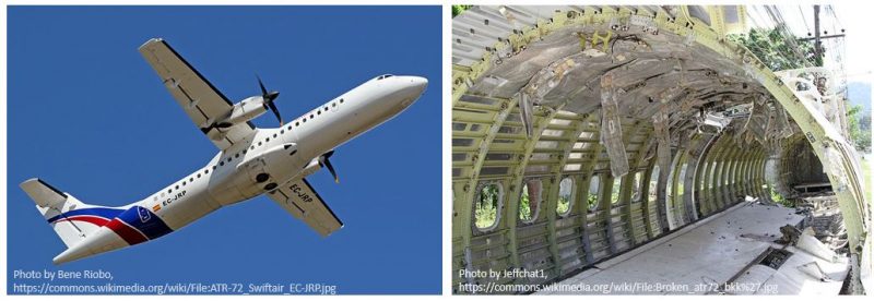
Semi-Monocoque
Somewhere between the space frame arrangement (skin takes no load) and pure monocoque arrangement (skin takes all the load) lies the semi-monocoque design which is the most common method of constructing aircraft structure today. In a semi-monocoque structure both the skin and set of frames are load carrying and contribute to the overall stiffness of the structure. This design methodology was born out of the use of aluminum rather than steel as the primary structural material used in the design of aircraft structures. Aluminum has many advantages over steel, principally its density is approximately one-third that of steel. For a constant structural mass, the aluminum sections can be thicker which reduces the susceptibility of those skins to buckling, which in turn produces a more efficient structure.
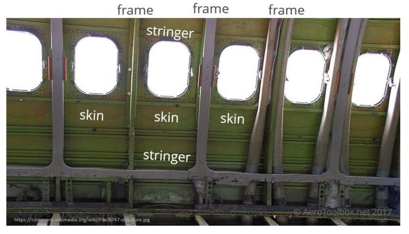
A semi-monocoque fuselage therefore typically consists of the following structural components:
- Frames - these transverse elements are built in the shape of the fuselage cross-section and are typically spaced approximately 20 inches or 50 cm apart.
- Stiffeners/stringers - the frames are joined to one-another by longitudinal stiffeners or stringers.
- Skins - the skin is load-bearing and gives the fuselage its form and shape. The skin is attached to the sub-structure on an aluminium aircraft by riveting it to the frames and stringers.
Semi-monocoque structures are the predominant way in which aircraft are designed and so the rest of this tutorial will focus on the application of semi-monocoque structures.
Fuselage Loading
A fuselage structure is loaded in a number of ways. These include:
- Aerodynamic loads as a result of the aircraft maneuvering through the air.
- The distribution of the mass of the fuselage induces bending
- Inertial loads created by point masses connected to the fuselage (engines attached to fuselage by a pylon is an example).
- Concentrated point loads: for example the interface between the fuselage and the tail.
- Internal pressurization loads (if the aircraft is pressurized).
- Shock loading: for example the nose landing gear impacting the runway on landing.
The loading experienced by the fuselage is likely a combination of each of these at a given moment in time. How then do each of the structural elements present in a semi-monocoque fuselage structure work together to distribute and transfer the resulting loading?
The frames work to support the skins and stiffeners against buckling while retaining the aerodynamic shape of the fuselage. Frames are also used wherever concentrated loads are introduced into the structure, for example at the wing-to-fuselage interface, and the tail-to-fuselage interface. Finally, frames are also used in conjunction with the skin to resist the internal pressure formed when an aircraft is pressurized.
Stiffeners and stringers are responsible for transmitting the axial loading (both tension and compression) that arise out of the bending moments induced through the fuselage structure. A good example would be the bending moment generated through the fuselage when applying a rudder input during flight. The stiffeners also assist in preventing the fuselage skin from buckling.
Finally the skins transmit shear loads and work to introduce load into the stiffeners. The skins also resist the internal pressure which is present in a pressurized aircraft.
To summarize:
Axial loads are carried by the longitudinal stiffeners and stringers
Shear loads are carried by the skin
The basic methodology behind the structural design of a fuselage is to ensure that the skin/stiffener combination does not buckle between transverse frames. Therefore the frames must be stiff enough that they do not buckle globally, and the skin and stiffeners, which form a series of segments on the fuselage, must not buckle locally. An optimized fuselage design results when these conditions are met for the lightest possible structure.
Fuselage Sizing
Let's move on from the various structural elements that are required to design a fuselage onto how you determine the size and shape of the fuselage required for your aircraft design.
A good starting point is to thoroughly understand the requirements of the aircraft that you are designing; here are some questions you should ask yourself:
- What does my payload look like? Am I designing a passenger aircraft, carrying cargo or munitions?
- How is my aircraft powered? Do I need to include space in the fuselage for an engine or will the engines sit externally on the wing or towards the rear of the fuselage?
- What does a typical mission for my aircraft look like? Am I more interested in achieving a high cruise speed at the expense of payload or is the size and extent of the payload the driving requirement?
- Is the aircraft to be pressurized or unpressurized? Pressurized aircraft generally have cylindrical fuselage cross-sections as this is the most efficient shape to resist the internal pressure.
Once you are clear which factors will drive the fuselage design you can start to sketch a preliminary outline of your fuselage. It is useful to start by first placing all the components that you know your fuselage will need to house e.g. engines, passengers, cargo etc, and then shaping the fuselage around these. Generally it is good to start by creating a number of cross-sections of your proposed fuselage over the critical components and then begin to join them up to form your preliminary design. Of course it is also very important to consider the location of the center of gravity of your fuselage and internal components, as the location of the aircraft C.G relative to the center of lift of the wing is a critical stability criterion.
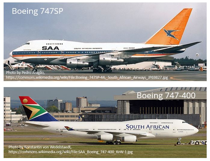
The placement of the wing and tail surfaces will also drive the total length of the fuselage both from a stability and a controllability standpoint. A longer fuselage means that the tail surfaces can be made smaller since the moment arm between the aircraft C.G and the aerodynamic center of the horizontal and vertical tail surfaces is increased, which increases the effectiveness of the control surfaces. This is very nicely illustrated when comparing the size of the vertical tail on the shorter Boeing 747SP to that of the 747-400.
Typically the fuselage contributes somewhere between 20 and 35 % of the total drag produced by the aircraft at cruise and this is a function of three key variables:
- The maximum cross-sectional area of the fuselage.
- The fuselage slenderness ratio (ratio of length-to-diameter).
- The total wetted area of the fuselage.
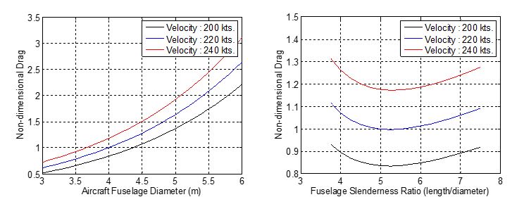
The effect that these variables have on the total profile drag of the fuselage is shown in the plots generated below:
An increase in fuselage diameter from 4 m to 5 m produces an increase in fuselage profile drag of 60 %. This illustrates just how important it is to size your fuselage in order to fit your intended payload but not make it unnecessarily larger.
The length of your fuselage should be sized according to the maximum cross-sectional area. A slenderness ratio (length-to-diameter) of between 5 and 6 produces the minimum drag case.
The location of doors and windows on the fuselage is another important consideration that must be carefully studied. The locations of the windows for example will affect the locations of the transverse frames through the fuselage. Anybody who has flown on a commercial airliner would argue that the locations of the windows are driven by the placement of the frames and not the other way around! The type, size, and minimum number of doors and emergency exits placed on the fuselage is specified by the regulations published by the Federal Aviation Authority. This is driven by the need to quickly and efficiently evacuate passengers in the event of an emergency. Doors and windows form cut-outs on the fuselage structure which requires additional reinforcement of the structure around these openings. This is turn results in a heavier structure and so the size and number of cut-outs should be kept to a minimum.
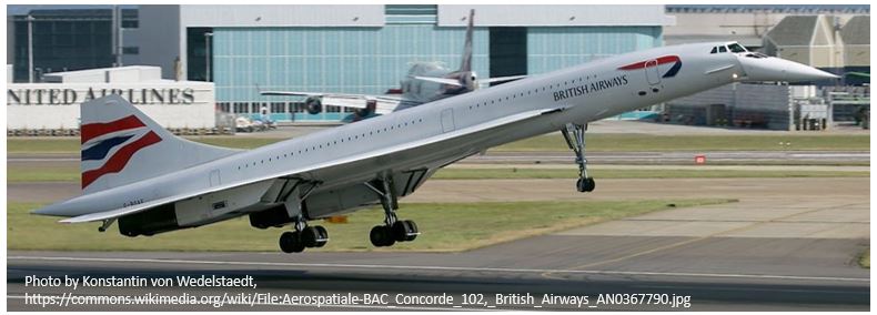
One additional but important consideration is the design of the cockpit. Pilot visibility is a major consideration (at least while commercial aircraft remain piloted) and the cockpit must be sized in order to allow the pilots to safely operate the aircraft at all times during flight. The approach and landing phase of the flight are the most critical from a pilot visibility perspective. During landing the pilot will pitch the aircraft nose up to increase the angle of attack of the wing in order to fly at a slower speed. Visibility of the runway at this attitude is an important factor that must be considered. Delta winged aircraft like the Concorde land at very high angles of attack, which is why the Concorde nose rotates downward during landing to allow the pilots to see the runway over the aircraft’s nose.
As with all aircraft design, the design of an efficient fuselage is a very iterative process that requires many loops until convergence is reached from a sizing, structural, aerodynamic and stability point of view. A well designed fuselage will be optimized for payload, weight, aerodynamic drag and the ability to stretch or shrink in length to accommodate new variations or configurations of the aircraft during its life.
Thanks for reading this introduction to fuselage design. If you enjoyed reading this please get the word out and share this post on your favorite social network!


