Introduction
Welcome to Part 6 of a series on an Introduction to Aircraft Design. In part 5 we looked at the role that the airfoil profile plays in determining the flying characteristics associated with its selection. In our final introductory post on the wing we look at a typical wing structure, the various loads that the wing is expected to carry during operation, and introduce the methodology behind designing a semi-monocoque wing structure.
The last three posts in this series have focused on the conceptual design of the wing. We examined wing area and aspect ratio, introduced sweep and drag divergence and looked in more detail how the airfoil profile determines the flying characteristics of the aircraft. In short, we have laid the groundwork to develop a conceptual design of a wing.
Before moving away from the wing we’ll now spend some time introducing the structural design elements that allow the wing to operate safely through all phases of the design envelope.
Loads acting on a Wing
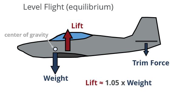
A wing is primarily designed to counteract the weight force produced by the aircraft as a consequence of its mass (the first post in this series deals with the fundamental forces acting on the aircraft). Thus during straight and level flight, the wing provides an upward lifting force equal to the weight of the aircraft plus the trim force generated at the horizontal tail to keep the aircraft balanced. The downward trim force comes about as a result of the need to balance the moment generated by the lift vector acting away from the center of gravity of the vehicle. In the conceptual design phase it is common to account for the additional force generated at the tail by multiplying the aircraft weight by a factor of 1.05 (5%) to account for the trim force; alternatively one can estimate the required force based on the estimated design weight of the aircraft and the approximate moment arm between the estimated location of the c.g. and the estimated location of the tail.
Load Factor
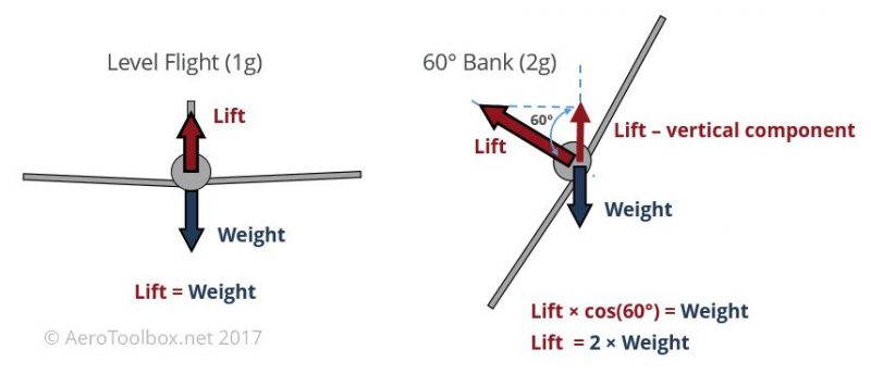
An aircraft does not just fly straight and level during all phases of operation. If the pilot banks the aircraft at a 60 degree angle during a sharp turn, he needs to produce twice the lifting force to counteract the weight due to the angle of the lift vector relative to the weight (which always acts downward). In this instance, the wing is producing a lift force equal to twice the weight of the aircraft and the aircraft is said to be pulling 2g’s (twice the gravitational force) or operating at a load factor of 2.
The example above illustrates that there are many cases where the aircraft will exceed a loading of 1g. The Federal Aviation Administration (among other regulatory bodies) is responsible for ensuring that all certified aircraft comply to a basic standard of safety. Therefore a series of regulations are published, which among other regulations, detail the minimum load factor that a particular aircraft class should be designed to withstand.
The following extract comes from FAR Part 23
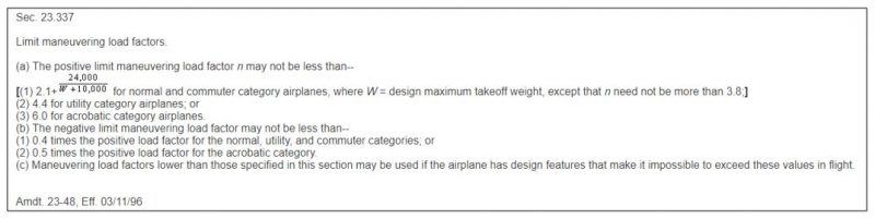
The minimum design limit load factor is a function of the classification of the aircraft that is being designed. For example, it follows that an aerobatic aircraft will require a higher limit load factor than a commuter aircraft due to the difference in the severity of the maneuvers the two are expected to perform.
The extract shown above pertains to an aircraft that is to be FAR Part 23 certified which is the airworthiness standard for Normal, Utility, Acrobatic, and Commuter type aircraft. Airliners and larger commercial aircraft do not fall into the FAR 23 category and so are certified in accordance with FAR Part 25 which is the airworthiness standard for Transport Category Aircraft.
Further to specifying the maximum maneuvering load factor, the aircraft must also be designed to withstand a gust loading during level flight. Gust loading is outside of the scope of this tutorial but the reader is referred to FAR 23.341 for further information.
Limit and Ultimate Loading
The maximum maneuvering load factor specified for an aircraft design is known as the aircraft limit load.
A limit load is defined as the maximum expected load that the aircraft will see during normal operation.
It is not sufficient to design an aircraft’s structure to be able to withstand a limit load as this leaves no margin of safety in the design. Limit loads are therefore multiplied by a factor of safety to arrive at a set of Ultimate Loads which provide for a safety margin in the design and manufacturing of the aircraft. The standard factor of safety for aircraft design is 1.5.
The ultimate load factor is therefore equal to 1.5 times the limit load specified in the FAR regulation.
FAR regulations stipulate that an aircraft must be able to withstand limit loads with neither any permanent deformation of the structure nor any detriment to safe operation of the aircraft.
Ultimate loads can result in plastic deformation of the structure but must be held for three seconds without failure.
Shear and Bending on a Wing
A wing is designed not only to produce a lifting force equal to the weight of the aircraft, but must produce sufficient lift equal to the maximum weight of the aircraft multiplied by the Ultimate Load Factor. So an aircraft that weighs 12 000 lbs and is designed to an ultimate load factor of 4.5 must thus be able to produce 54 000 lbs of lift up to a speed governed by the FAR regulations (dive speed). There will be a minimum speed below which the wing is incapable of producing the full 54 000 lbs of lift and this is governed by the maximum lift coefficient of the wing and resulting stall speed. In reality a V-n diagram is constructed which graphically illustrates the flight envelope of the aircraft. We wont' discuss the V-n diagram in this introductory post.
Once the maximum lifting force that wing is expected to produce has been established, the distribution of that lifting force over the span of the wing is estimated. The lift distribution over a conventional wing is parabolic in nature, rising from the tip and reaching a maximum at the root.
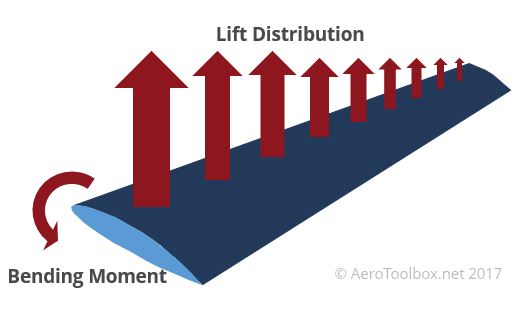
This resulting vertical force distribution over the span of the wing causes the wing to flex and bend upward when it is loaded. If you look out of the window and at the wing of a modern airliner like the Boeing 787 during takeoff and landing you are sure to see a high degree of flexing. The lift produced by the wing results in a large bending moment at the wing root that must be transferred to the wingbox (the structure that connects the wing to the fuselage).
There are therefore two primary types of loading that the wing structure must be designed to withstand.
- A vertical shear force due to the lift generated.
- A bending moment arising from the lift distribution.
The wing is also subjected to torsional loads arising from the pitching moment formed by the offset between the center of pressure and the attachment points of the wing, and horizontal (in-plane) shear forces as a result of the drag force acting on the wing. This introduction will concentrate on the vertical shear and bending moment as these loads generally drive the wing design. However, the torsional load should always be accounted for when performing a shear flow analysis to size the wing skins and shear webs.
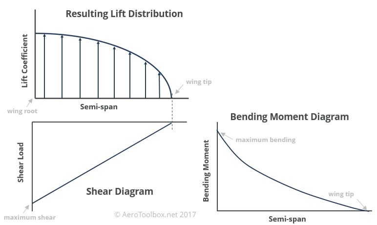
An example of the distributed lift load and resulting shear and bending moment diagrams arising from this loading is shown below. In both cases it is clear that the location of the highest shear and bending is the wing root.
Wing Structural Components
The primary objective of the wing’s internal structure is to withstand the shear and bending moments acting on the wing at the Ultimate load factor. The secondary objective is to make the wing as light as possible without compromising the structural integrity of the design as described above.
An optimized wing design will fail just as the ultimate loading conditions are reached.
There is no need to make the wing any stronger than it needs to be, and any excess strength (wing weight due to extra material) will reduce the payload capacity of the aircraft making it uncompetitive or uneconomic to operate. In reality the wing will be analysed using computational methods for many different loading combinations that exist at the edge of the aircraft design envelope and then subjected to a static test at the ultimate load factor to show that failure will not occur below the ultimate load.
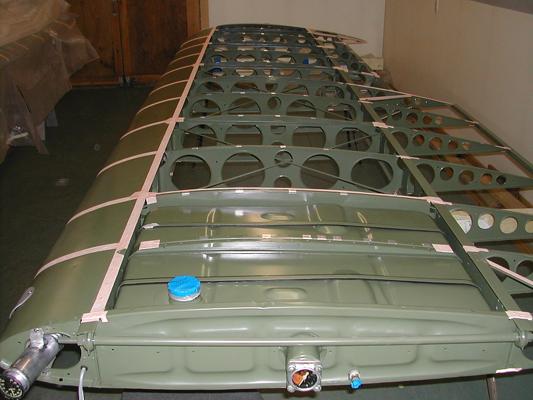
An aircraft wing is usually designed with a semi-monocoque approach where all the components making up the wing structure are load bearing. A typical semi-monocoque wing structure is shown below with the various components labelled:
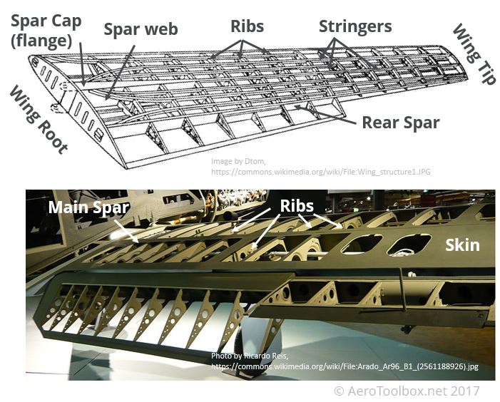
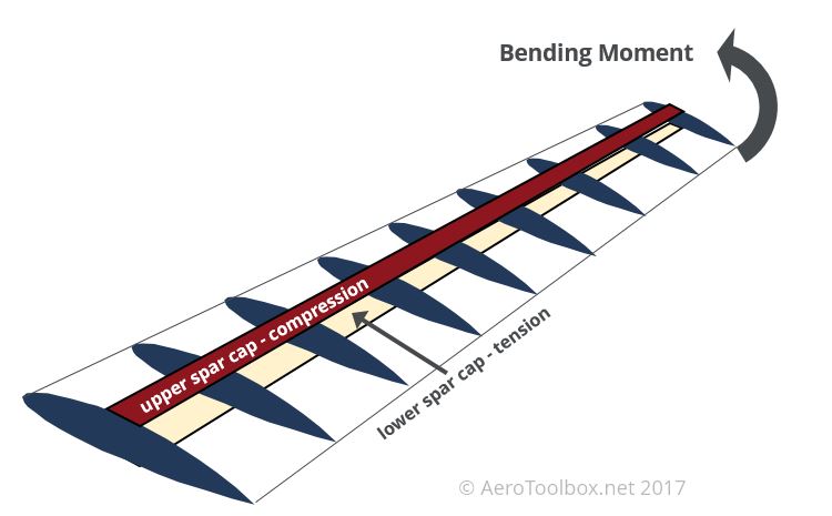
Spar Cap (flange)
These consist of the upper and lower flanges attached to the spar webs. The spar caps carry the bending moment generated by the wing in flight. The upper spar cap will be loaded in compression and the lower in tension for a positive load factor (wing bending upward). The spar caps also form a boundary onto which wing skin is attached and support the wing skin against buckling. Concentrated load points such as engine mounts or landing gear are attached to the main spar.
Spar web
The spar web consists of the material between the spar caps and maintains a fixed spacing between the them. This allows the spar caps to act in pure tension and compression (bending) during flight. The spar web is responsible for carrying the vertical shear loads (lift) which arises from the aerodynamic loading of the wing. The spar webs and caps are collectively referred to as the wing spar.
Wing Ribs
The ribs are spaced equidistant from one-another (as far as is practical) and help to maintain the aerodynamic profile of the wing. The ribs form part of the boundary onto which the skins are attached, and support the skins and stiffeners against buckling. Ribs also form a convenient structure onto which to introduce concentrated loads
Stringers/Stiffeners
Stiffeners or stringers form a part of the boundary onto which the wing skin is attached and support the skin against buckling under load. The stiffeners also carry axial loads arising from bending moments in the wing.
Skin
The wing skin transmits in-plane shear loads into the surrounding structure and gives the wing its aerodynamic shape.
Analysis Methods
What follows is a brief introduction into some methodologies and analyses typically carried out during the design of a new wing structure. We will not go so far as to look into the specifics of the mathematics used, but will discuss the preliminary structural layout of the wing and look at two analysis methods that drives the structural design: a shear flow analysis and a collapse moment analysis.
Preliminary Structural Layout
Before the structural layout of the wing is designed, a preliminary sizing of the wing planform should have been completed to size the wing for its required mission. If you have been following along from the start of this series then you’ll be familiar with sizing a wing with respect to plan area and aspect ratio, sweep and supersonic flight, and selecting a suitable airfoil profile in order to complete the planform design of the wing.
Once the planform is frozen, a preliminary structural layout should be drawn up using the following rules of thumb:
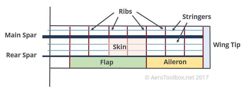
- Generally the main spar is located at or near the 25 % chord location. The aerodynamic center of the wing exists at approximately quarter chord which is the location on the wing where the moment coefficient is independent of angle of attack. It is good design practise to locate the main spar near the aerodynamic centre.
- A rear spar is often required in order to attach the trailing edge flap and aileron surfaces to the main wing structure. If the surfaces have already been specified during the conceptual phase (before the structural design is started) then these surfaces will form a natural constraint and drive the placement of the rear spar.
- Ribs will need to be placed at any points in the wing where concentrated loads are introduced. Common examples such as engine pylons, landing gear, and flap and aileron junctions should guide the placement of the first few ribs.
- Additional ribs should be placed equidistant along the span of the wing such that the aspect ratio between the ribs and the skin remains close to one. This aids in unloading the shear in the skin and reduces the tendency for the skins to buckle.
- Stringers can be added between the spars. This will aid the skin in resisting shear buckling.
A layout for a simple rectangular wing is shown below taking into account the rules of thumb described above.
Structural Idealization
In order to efficiently analyse the wing structure, a number of simplifying assumptions are typically made when working with a semi-monocoque structure.
The spar caps/flanges and stiffeners only carry axial (bending) loads.
The skins and spar web only carry shear loads.
This is the classical approach to aircraft structural design and will result in an efficient structure that has been sized with conventional methods which are well accepted by the certification authorities. However, improvements in computing power along with the rise of composite materials in structural design means that there is a gradual movement away from the classical methods to analyzing the structure in such a way that seeks to further optimize the design to produce the lightest possible structure. We’ll just focus on the classical methods for the sake of this tutorial.
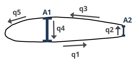
Shear Flow Analysis
Examining the mathematics behind a shear flow analysis is outside of the scope of this introductory tutorial; rather the methodology and rationale will be discussed.
A shear flow analysis is used to size the thickness of the wing skin and shear webs. A shear force diagram is determined at the maximum load factor which then serves to specify the variation in shear force along the span of the wing. The variation in shear force along the span forms the input into the calculation as the shear at each spanwise location must be transferred into the wing structure.
Based on the assumption that the skin and web only transmits shear and no axial load, the shear stress within a skin panel will remain constant where ever the thickness of the skin is constant.
The product of the shear stress and the thickness is therefore constant along a skin and is termed shear flow.
$$q = \tau \times t$$
Where: \( q: \) Shear flow \( (N/mm) \)
\( \tau: \) Shear Stress \( (N/mm^2) \)
\( t: \) Skin thickness \( (mm) \)
A panel section of the wing can therefore be modelled as a set of skins where thickness is a variable, and once the shear flows acting on each of the skins are known, the thickness of the skins can be varied until the shear stress in each skin is below the material allowable shear stress. In this way, the wing skins and web will not fail as a result of the shear loading induced when the aircraft operates at the edge of the design envelope.
The final skin shear flows are also a function of the spar cap area, and this can also be varied to manipulate the final shear flows.
Collapse Moment Analysis
As with the shear flow analysis, the mathematics behind this calculation are complex and outside of the scope of this tutorial. Instead we briefly introduce the rationale behind a collapse moment analysis.
As described above, a shear flow analysis is used to size all the shear components of the wing structure (webs and skins). We now examine the bending components of the design; namely the spar cap areas and the propensity of the skins on the upper surface of the wing to buckle under compression at high load factors.
The spar caps are responsible for transferring the bending moment generated by the wing into the surrounding structure. When the wing is subjected to a positive load factor it will tend to deflect upward and load the upper spar caps and skin in compression, and the lower structure in tension.
A collapse moment analysis examines the interaction between the wing skin in compression (which will tend to buckle) and the ability of the spar caps to absorb the extra load transferred if the skins do buckle. Buckling of the skin does not necessarily result in failure of the whole wing structure as the buckled skin will transfer load into the spar caps and stiffeners that border the skin. This transfer is accomplished through shear flow.
The wing will fail when the stress in the stiffeners or spar caps reach their maximum crippling (failing) stress. The problem becomes an iterative one as the stress at which the skin first starts to buckle must be determined, which in turn affects how much additional load is transferred into the spar caps.
The critical bending moment at which the spar cap/stiffener will reach its critical stress and fail is a function of the cross-sectional area of the stiffener and also the distance that the stiffener lies from the neutral axis. The position of the neutral axis is in turn a function of the extent to which the skins have buckled on the application of the maximum load.
The moment at which the structure will collapse is determined once the crippling stress (critical stress in spar cap) and the moment of inertia (function of extent to which skins have buckled) is known.
This collapse moment is then compared to the bending moment diagram generated for the wing to ensure that the bending moment applied is lower than the collapse moment at all spanwise locations of the wing.
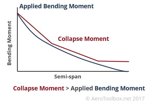
Since the bending moment is a maximum at the root of the wing, the spar caps will need to be large enough (sufficient area) so as not to fail in bending. Using a constant sparcap area from root to tip would result in a situation where the applied bending moment is very much smaller than the collapse moment as one moves toward the tip. This would result in an inefficient structure which is overly heavy.
One way to mitigate this is to reduce the spar cap area as one moves toward the wing tip in such a manner that weight is reduced but the collapse moment is always greater than the applied moment at all points along the wing. Additional spar cap area serves to increase the moment of inertia at that cross-section of the wing, allowing the wing to resist larger bending moments.
Wrapping Up
Completing the full structural design of a new wing is a complex and iterative process. The analysis described above just represents a small part of the design and stress analysis process. A wing structure would be modeled using a Finite Element (FE) package and tested for many different load combinations before a prototype is built and tested to the point of destruction as a means to validate the paper calculations and computer analysis. However, starting with some hand calculations, similar to those shown above is a good way to begin the design process as it ensures that the engineer understands the resulting load paths before creating an FE model.
Thanks for reading this Introduction to Wing Structural Design. If you enjoyed reading this please get the word out and share this post on your favorite social network!


