Introduction
The concept of wing sweep was introduced in the previous post which discussed the concepts of Wing Area and Aspect Ratio and their importance in the design of a new aircraft. We'll now spend some time looking at wing sweep and discuss how correctly applying a sweep angle to a wing is a necessity if you are designing an aircraft that operates anywhere near the transonic or supersonic region.
A wing is said to be swept when a straight line between two corresponding chord locations (given as percentage of chord) on the root and the tip are angled relative to the lateral coordinate of the aircraft. This is most easily seen when viewing the wing in planform as shown on the Boeing 747-400 below.
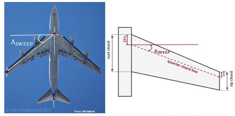
The sweep angle of a wing is the angle at which the wing is translated backwards (or occasionally forwards) relative to the root chord of the wing.
Why Sweep a Wing?
Wing sweep is primarily used on aircraft that fly in the transonic and supersonic regions. The sweep has the effect of delaying the formation of shock waves on the surface of the wing caused by the compressibility of air at high speeds. The ability to delay the formation of the shock waves has a dramatic positive effect on the total drag produced by the aircraft as it approaches Mach 1.
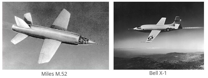
Early attempts to fly at sonic speeds in straight-winged aircraft were characterised by a noticeable drag increase and violent shuddering of the airframe as these high speeds were approached. While the first aircraft to break the sound barrier, the Bell X-1, made use of a straight wing, it required a rocket engine to produce sufficient thrust to overcome the large drag rise and suffered from controllability issues at high speed. In fact, the British equivalent to the Bell X-1, named the Miles M52 was cancelled once the benefits of swept-wing technology came to light.
The idea of sweeping a wing to reduce the onset of compressibility effects and to delay the formation of shock waves came from a German scientist Dr. Adolf Busemann who presented his findings at the Volta Conference in Italy in 1935. He described how the aerodynamic properties of the wing are dominated by the component of air flow normal to the leading edge of the wing section and not the freestream velocity. Thus by sweeping the wing back, one could reduce the velocity component over the wing which would therefore delay the formation of shockwaves at high speed as the wing would be seeing an effective velocity less than the actual freestream velocity.
The swept wing shown in the image below decreases the velocity normal to the leading edge by almost 30 % of the freestream velocity at a sweep angle of 45°. Since the velocity normal to the leading edge is responsible for the magnitude of the pressure distribution over the top and bottom surface of the wing, it follows that the reduced velocity \(U_{N} \) will result in a smaller pressure difference between the two surfaces and consequently a reduction in the lift produced by the swept wing all other things being equal. This is a simplification of the actual flow distribution as the discontinuity at the wingtip and other effects like interference between the wing root and fuselage are neglected; however, the essential flow dynamics and central idea behind wing sweep are well captured by this explanation.

Shockwave Formation
To understand how and why shockwaves form as an aircraft approaches sonic speeds you need to appreciate that air is a fluid and that it is compressible. At low speeds (generally below Mach 0.5) air is essentially incompressible which allows scientists and engineers to make a number of simplifying assumptions when modelling the motion of the aircraft through the air. The chief assumption when modelling fluid flow as incompressible is that the density of an infinitesimally small parcel of that fluid is constant in time.
However, as an aircraft approaches transonic speed, the pressure waves associated with the motion of the aircraft through the air begin to converge and compress the air ahead of the aircraft. Here the simplifying incompressible assumptions are no longer valid.
This compression of the air creates an additional drag force termed wave drag. This is the component of drag due to the presence of shockwaves and dominates the total drag summation at high speeds. This wave drag increases exponentially as the aircraft approaches Mach 1.0 before reducing once all the airflow around the aircraft is supersonic.
A shockwave forms when the local airflow around the aircraft reaches sonic speed (Mach 1). It is characterised by a discontinuous change in pressure, temperature and density across the medium in which it forms.
The formation of shockwaves requires a lot of energy which has to be overcome by a large increase in thrust as the speed of sound is approached.
Shockwaves form in regions where the local velocity is sonic and as such will begin to form before the overall aircraft velocity is sonic. Regions of curved surfaces such as over a canopy or on the upper surface of the wing causes the air to accelerate and create local regions of sonic flow which result in the localized formation of shockwaves. This typically occurs at airspeeds upward of Mach 0.8 (transonic region).
Sweeping the wing assists in delaying the formation of a shockwave on the upper surface of a wing, by reducing the normal airflow component over the wing. Typically shockwaves will form just after the point of maximum thickness on a wing airfoil profile which is why commercial airliners that cruise in the transonic region make use of supercritical airfoil sections which are flatter on the upper surface to delay the formation of the shockwave.
Since shockwaves form in regions where the local velocity is sonic, every aircraft will have a critical Mach number which is defined as the lowest speed at which the airflow over some region on the aircraft exceeds the speed of sound. Below the critical Mach number all airflow around the aircraft is subsonic, and at the upper critical Mach number all airflow around the aircraft is supersonic.
Near the critical Mach number is the drag divergence number which is the Mach number at which the total aerodynamic drag begins to increase rapidly as the Mach number increases toward Mach 1.0. The name comes from the fact that the total drag rapidly diverges from the well established subsonic methods due to the formation of shockwaves and the accompanying increasing wave drag.
Selecting a Sweep Angle
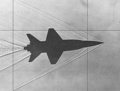
Shockwaves can broadly be characterised as either normal or oblique. Normal shock waves form perpendicular to the surface which triggers the shock (an example would be the upper surface of a wing) while an oblique shock wave is inclined at an angle to the incident upstream flow direction. This would occur when a supersonic flow encounters a corner that causes the flow to turn into itself and compress. Oblique shocks form on pointed wedges such as on the nose of an aircraft. The airspeed downstream of a normal shock must always be subsonic while the Mach number behind an oblique shock can be either supersonic (weak shock wave) or subsonic (strong shock wave). Careful design of the aircraft geometry in such a manner so as to use the resulting shockwaves to slow the air to a subsonic state is a well established method for ensuring that a subsonic wing profile will perform as intended even when the aircraft is flying supersonic.
The angle that the oblique shock makes is a function of the speed that the aircraft is travelling. At Mach 1.3 the angle is approximately 45°, and this increases to 60° at Mach 2. If the cruise speed or typical operating speed of the supersonic aircraft being designed is known, one can sweep the wing such that at the supersonic design speed, the wing is subjected to subsonic airflow and as such will behave as it would when flying at subsonic speeds. If the wing leading edge is inside the subsonic flow cone formed by the shockwave, the wing is termed to have a subsonic leading edge. If all or a part of the wing is inside the supersonic region the wing has a supersonic leading edge.
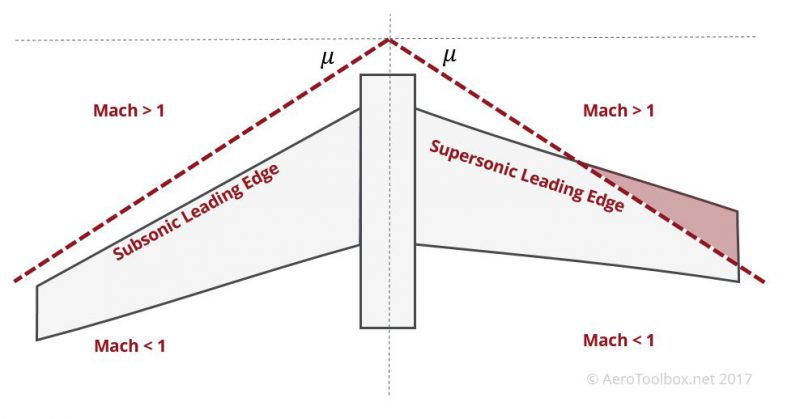
A supersonic leading edge results in a powerful normal shock forming on the leading edge in the supersonic region which creates a large drag rise over the wing and hinders the typical operation of the wing. Conversely, a subsonic leading edge will allow the upper and lower wing surfaces to interact with one another as they would in subsonic flow; even though the freestream Mach number is greater than one. Careful design of the aircraft geometry will result in successive weak oblique shocks which bring the airflow over the wing to a subsonic speed. This results in a smaller drag rise than a normal shock on the wing leading edge.
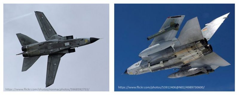
There is an important trade-off and design compromise to be aware of when selecting the sweep angle. A highly swept wing that has a completely subsonic leading edge will perform very well at supersonic speeds but at the cost of slow speed subsonic performance. A swept wing produces less lift than an equivalent unswept wing which results in both a higher stall speed and a less maneuverable platform. This is why aircraft such as the F-14 Tomcat and Panavia Tornado make use of a variable sweep or swing wing to optimize both for supersonic performance and subsonic maneuverability.
Since commercial airliners cruise in the transonic region above Mach 0.8, sweep angles are typically less than 40°. Fighter aircraft capable of speeds in excess of Mach 1.5 generally are designed with sweep angles up to 60°.
| Aircraft | Operating Mach number | Wing Sweep Angle (°) |
|---|---|---|
| B737-400 | 0.75 | 25.0 |
| B767-300 | 0.80 | 31.5 |
| TU-95 Bear | 0.78 | 35.0 |
| A330-300 | 0.82 | 30.0 |
| B777-300ER | 0.84 | 31.6 |
| B747-400 | 0.85 | 37.5 |
| A380-800 | 0.85 | 33.5 |
| F-22 | 1.80 | 42.0* |
| F-16 | 2.00 | 40.0* |
| MiG-21 | 2.00 | 57.0* |
| Mirage 2000 | 2.20 | 58.0* |
The positive and negative effects associated with adding sweep to a wing design are summarized below:
- Sweeping the wing of any aircraft that is travelling at speeds in excess of Mach 0.5 - Mach 0.6 is necessary to avoid very large increases in drag as a result of the formation of shockwaves in regions where the flow is locally accelerated to speeds in excess of Mach 1.
- Aircraft designed to operate at supersonic speeds make use of the geometry of the aircraft to slow the air flowing over the wing to subsonic speeds in order to ensure that the wing is able to produce the lift required to keep the aircraft flying without a large spike drag spike associated with the formation of normal shocks on the wing leading edge.
- Sweeping a wing has negative implications when flying at subsonic speeds. Sweep reduces the aspect ratio of the wing which is associated with a larger induced drag component during subsonic operation. The sweep also reduces the effective airflow component going over the wing which results in less lift being produced at a given angle of attack and a subsequent increase in the aircraft stall speed.
Thanks for reading this introduction to wing sweep and shockwave formation. If you enjoyed reading this then it would be great if you could share this on your favourite social network!


