Welcome to part two in this five-part series on airframe structures. In this post we’ll be focusing on the fuselage; specifically, we discuss the design of a typical semi-monocoque structure, and the various structural components and loadings that contribute to the final design.
If you missed part one, then perhaps go back and read this before continuing as this provides an overview on structural loading and design.
The wing is covered in part three, flaps in part four, and the tail in part five.
Introduction
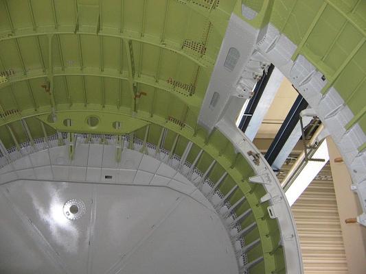
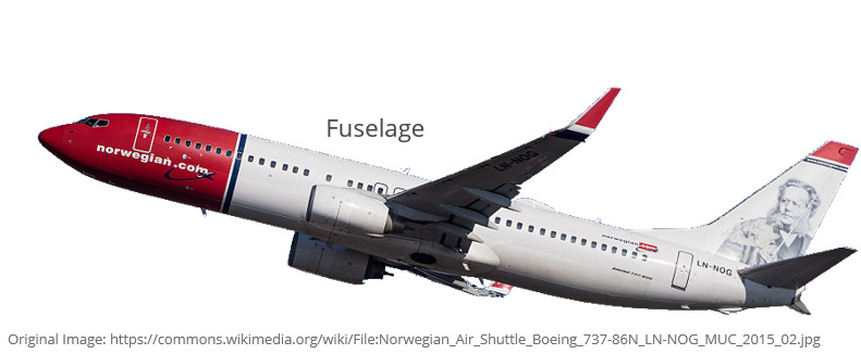
The fuselage is the name given to the main body of the aircraft and houses the pilots, crew, passengers, and cargo. The wings and tail section are attached to the fuselage, and depending on the design of the aircraft, may include engine attachments too.
The fuselage does more than just house the occupants of the aircraft; it must be sized and designed to ensure that the wings and tail are positioned in such a way so as to keep the aircraft statically stable through the designed center of gravity envelope. A statically stable aircraft is one that will tend to return to straight and level flight if the controls are released, which is a requirement for all civil and general aviation aircraft.
The fuselage is one of the primary contributors to the total drag force produced by an aircraft in flight and so must be carefully shaped to be as aerodynamic as possible in an effort to minimize drag. There is of course some balance that must be sought between low aerodynamic drag and payload and passenger comfort.
The fuselage structure must be sufficiently strong to ensure safe operation throughout the flight envelope. A semi-monocoque structural design is usually favoured; where the sub-structure and the skins work together to absorb and transfer the loads generated during flight.
Semi-monocoque Fuselage
The various structural design methodologies were discussed in part one of this series. Here we are only going to consider the semi-monocoque design philosophy, and how it relates to the fuselage structure.
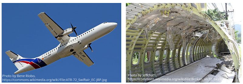
In a semi-monocoque structure both the outer skin and the internal substructure are load bearing, and both contribute to the overall stiffness of the structure. This design methodology was born out of the use of aluminium, rather than steel or wood, as the primary structural material used to manufacture airframe structures. Aluminium has many advantages over steel. The density of an aluminium alloy is approximately one-third that of steel which allows for thicker structural sections to be built without any weight penalty. Thicker skins are advantageous as these are less likely to buckle under load, resulting in a more efficient structure.
Structural Components
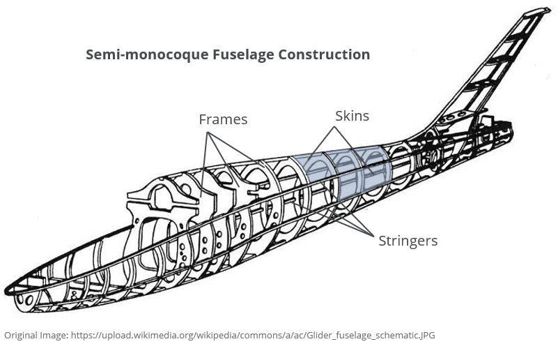
A typical semi-monocoque fuselage consists of the following elements:
Stringers or Longerons
These make up the longitudinal components of the structure. Their primary aim is to transmit the axial loads (tension and compression) that arise from the tendency of the fuselage to bend under loading. The stringers also support the skin, and when combined with the frames, create bays over which the skin is attached.
Frames
Frames are transverse elements that define the cross-section of the fuselage. They are typically spaced approximately 20 inches apart and define the aerodynamic shape. The frames and stringers are spaced in such a way to ensure that the resulting bays that are created support the skins against buckling. Frames also provide a means to introduce point loads into the fuselage. Large frames are required at the wing-fuselage and tail-fuselage interface to transmit the loads generated by these lifting surfaces into the fuselage.
Skins
The load-bearing skins are attached to the stringers and frames of an aluminium aircraft through rivets. The skins carry load through shear and transmit this shear into the stiffeners. In a pressurized aircraft the skin works with the frames to oppose the internal pressure load. The skin’s ability to carry and transmit shear is reduced if the skin is allowed to buckle; this forms a constraint that determines the spacing of the stringers and frames.
Fuselage Loading
The fuselage will see a combination of loads from multiple sources during a typical flight. Large bending loads are introduced from the wing and tail sections, as well as a torsional load from the pitching moment of the wing.
The fuselage generates its own aerodynamic loads during flight which must be reacted by the structure. These external pressure loads combine with internal pressure loads if the aircraft is pressurized.
Landing loads introduced into the fuselage can be particularly severe if the landing is executed poorly.
Finally, crew and passenger movements, as well as baggage requirements should also be considered in the final structural layout and design.
All these load cases, and the interaction between cases must be considered to arrive at a final design. The structure must be strong enough to withstand these loads at the Ultimate Load Factor determined by the applicable airworthiness regulations in order to ensure the safety of the crew and passengers.
Thanks for reading. If you enjoyed this post or found it useful as a study aid, then please introduce your colleagues and friends to AeroToolbox.com and share this on your favourite social media platform.


