This is the final tutorial in a five-part mini-series on airframe structures and control surfaces. The previous tutorial focused on wing flap and slat systems. We end this mini-series off with a discussion on the aircraft’s tail section with a focus on the tail’s impact in three primary areas: stability, control, and trim.
Why Does and Aircraft Have a Tail?
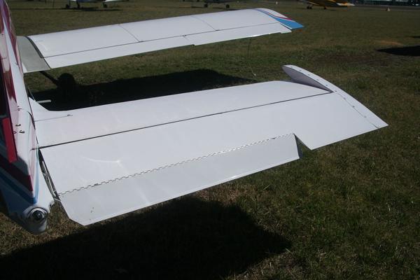
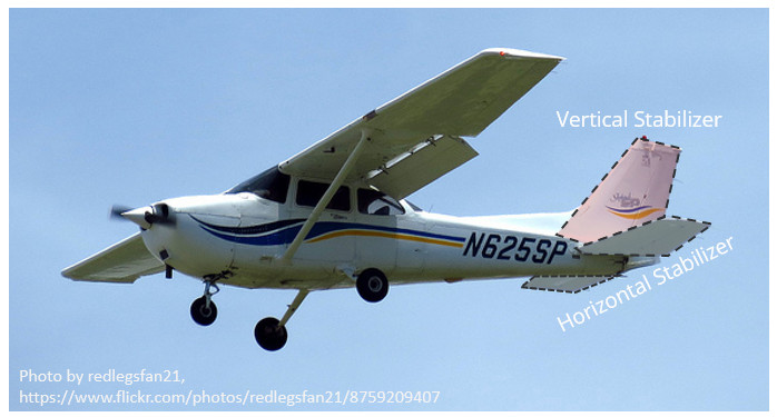
A conventional aircraft tail consists of two lifting surfaces oriented at right angles to one-another: a horizontal stabilizer and a vertical stabilizer. Together they are referred to as the empennage, which has French origins and translates to “feather an arrow”. This is a good description of the tail section, as like the feathers on an arrow, the empennage stabilizes the aircraft in flight.
The tail section has two primary objectives: (1) to provide stability in the longitudinal (pitch) and directional (yaw) plane, and (2) to control the aircraft’s pitch and yaw response through movable control surfaces attached to the horizontal and vertical stabilizers.
Stability
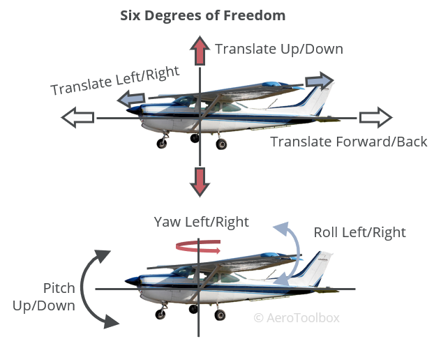
An aircraft in flight has six degrees of freedom: three translational degrees (forward/back, left/right, up/down) and three rotational degrees (pitch, yaw, roll). The tail controls pitch in the longitudinal plane, and yaw in the directional plane. An aircraft’s response to a control input is not isolated to that surface and so there are secondary control responses induced by surface deflection at the tail; for example, a yaw through a rudder input will induce roll as a secondary response if not corrected. In this tutorial we are only going to discuss the primary responses to control surface deflection at the tail surfaces. The horizontal and vertical stabilizers are both lifting surfaces and are usually constructed in very much the same manner as the wing with a main spar, ribs, and load-bearing skin.
Longitudinal Stability – Horizontal Stabilizer
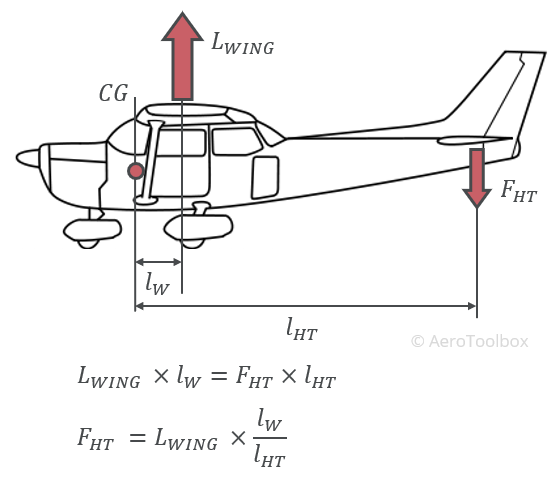
The need for a horizontal stabilizer becomes clear once the vertical forces acting on the aircraft during flight are plotted. An aircraft with a horizontal stabilizer situated to the rear of the fuselage is always designed such that the center of gravity (c.g.) sits ahead of the wing’s center of lift. In this configuration the wing imparts a nose-down pitching moment on the aircraft, with a magnitude equal to the resulting lift force multiplied by the moment arm between the center of lift and the c.g.
This nose-down pitching tendency is crucial to ensure the aircraft is stable in the longitudinal plane. Any time the aircraft’s nose pitches up, the wing will provide a restorative moment that will tend to bring the nose back down. This is termed longitudinal static stability (pitch stability) and is one of the hallmarks of a safe and stable airplane.
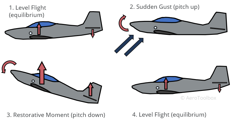
This resultant nose-down pitching moment must be balanced in flight to keep the aircraft flying straight and level. To balance the pitching moment at the wing, a moment of equal magnitude but opposite direction is generated at the horizontal stabilizer to keep the aircraft in trim. This requires that a downforce be generated at the horizontal stabilizer on a conventionally laid out aircraft where the tail is located aft of the wing. The moment is a function of the force at the tail multiplied by the moment arm between the c.g. and the stabilizer. The longer the moment arm, the smaller the downward force that must be generated to keep the aircraft in balance. This control surface deflection and downforce at the tail generates an induced drag which contributes to the overall drag of the aircraft. Placing the tail at a sufficient distance from the aircraft c.g. helps to minimize this drag force.
Directional Stability – Vertical Stabilizer
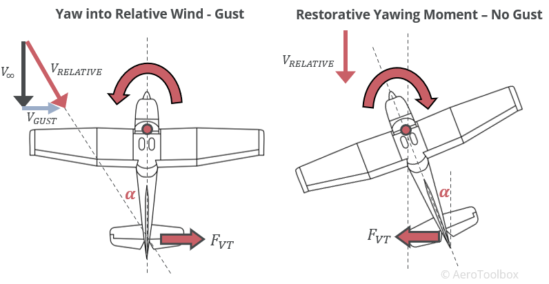
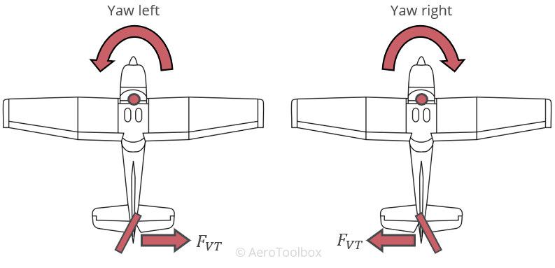
The vertical stabilizer controls the aircraft’s directional stability (yaw axis). The vertical lifting surface is symmetrical so that no net force is generated when the aircraft is aligned with the relative wind. The surface works in the same manner as the rear fin on a weathervane and causes the aircraft to always align itself with the relative wind. This is a stabilizing condition when the aircraft is exposed to a gust or side load as demonstrated below.
The relative wind is comprised of a vector consisting of the forward velocity of the aircraft and any side or gust load experienced as a result of the movement of air in the atmosphere. As the aircraft experiences a gust, the location of the tail behind the center of gravity causes the vertical tail to be instantaneously inclined at an angle of attack to the relative wind. This induces a force at the tail which causes the nose of the aircraft to swing into the wind. As soon as that gust disappears, the aircraft is once again inclined at some angle of attack to the new relative wind, and the nose swings again aligning the nose with the relative wind.
Control Surfaces
Stabilizing the aircraft in flight is one of the two primary objectives of the tail surfaces. The other is to provide a platform from which to control and manipulate the aircraft’s flightpath. Both stabilizers are fitted with a primary control surface; an elevator to control pitch on the horizontal stabilizer, and a rudder to control yaw on the vertical tail. In some cases, the entire horizontal stabilizer rotates about its mounting point to provide pitch control. This is termed a stabilator or an all moving tail. Some aircraft have combined the function of a horizontal and vertical stabilizer into a V-tail. The control surface attached to a V-tail is sometimes termed a ruddervator which is a composite of a rudder and elevator.
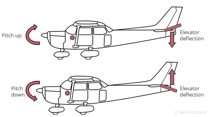
All control surfaces work by modifying the camber of the surface through a deflection of the trailing edge. This results in the generation of a force normal to the surface, which is orientated vertically on the horizontal stabilizer (lift or downforce) and horizontally on the vertical stabilizer (side force). This force acts over the distance between the control surface and the aircraft c.g. and induces a control moment, changing the aircraft’s pitch attitude (elevator) or yaw angle (rudder).
Trim
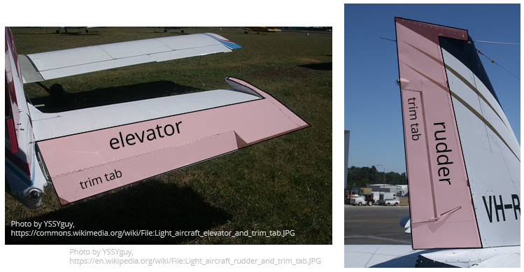
A trim tab is a secondary movable control surface that is affixed to the primary surface. This allows the pilot to manipulate the position of the primary surface, such that the aircraft will remain in a fixed aerodynamic configuration with the pilot’s hand off the control column. A trim tab on the elevator is fitted to almost all modern aircraft and is used by the pilot to maintain a desired pitch attitude during flight. A rudder may also be trimmed to counteract the torque effect of the engine, and some aircraft make use of trim tabs on the ailerons for roll control.
Elevator Trim
Trim Tab
We have already discussed the need for a vertical load on the horizontal stabilizer to balance the pitching moment generated by the wing. It is not feasible for the pilot to maintain a constant pressure on the control column throughout the flight to keep the elevator inclined at the precise angle required to maintain this force. Rather a trim tab is used to hold the elevator at the required angle by balancing the hinge forces without constant pilot input.
The pilot first moves the control column to the position that allows the desired aircraft attitude to be maintained. At this position, the pilot must exert a force on the column to maintain the angle of the control surface. A trim control in the cockpit is then operated by the pilot, which moves the trim tab, until the stick force has been removed.
The trim tab on the control surface will always move opposite to the surface that it is removing force from. This is best explained by referring to the diagram below.
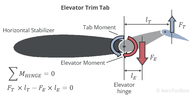
If the pilot wants to pitch the nose of the aircraft up, he pulls back on the control column which deflects the elevator trailing edge upward, producing a downforce at the tail which raises the nose. The pilot then trims the elevator to hold that deflection angle. The trim tab deflects downwards, causing a lifting force on the tab, which produces a moment at the elevator hinge equal and opposite to the moment generated at the hinge by the elevator force. The elevator position is held by the force generated by the tab and the pilot is able to relax the pressure on the control column.
Balance and Anti-balance Tabs
Depending on the sensitivity of the aircraft to pitch inputs, it may be necessary to assist or retard the movement of the elevator to improve the handing qualities of the aircraft.
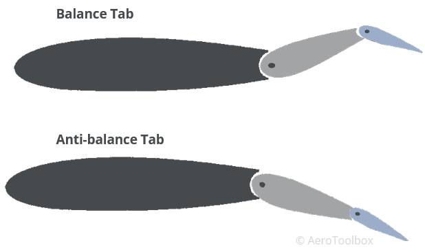
Balance tabs are rigged to operate automatically with application of the elevator and assist the pilot in reducing the control force necessary to move the elevator. They work in much the same way as a conventional trim tab, moving opposite to the direction of the elevator and reducing the overall moment that the pilot must apply through the control column.
Anti-balance tabs work opposite to a balance tab and retard the effect of moving the elevator by moving in the same direction as the elevator. These devices are most common on all-moving tailplanes (stabilators) where the large control surface area produces a situation where the pitch response to a control input is greater than what is required by the pilot. The anti-balance tab works against the control input, preventing over-control.
Fixed or Adjustable Tabs
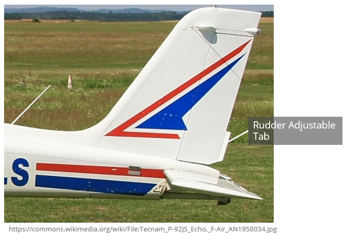
Common on rudders and some ailerons, these small metal tabs are affixed to the trailing edge of the control surface and are bent into position while still on the ground to counteract unwanted roll or yaw tendencies in flight. Adjustment occurs through a trial and error basis. Fixed tabs are often used on a rudder to counteract the torque effect of the engine, and to reduce the amount of rudder input required to keep the aircraft balanced.
This brings us to the end of this post and the end of our series on airframe structure and control surfaces. If you enjoyed this post or found it useful as a study aid, then please introduce your colleagues and friends to AeroToolbox.com and share this on your favorite social media platform. Thanks for reading.


