This is part four in of a five-part series on airframe structures. In the previous tutorial we discussed the wing structure, now we will focus exclusively on the aerodynamics and structural design of the high lift flap and slat system.
Introduction
Almost all modern aircraft make use of a high-lift system to provide additional lifting capacity at slow speeds. This system takes the form of trailing edge flaps, leading-edge slats, or a combination of both. Slats are rarely used on light aircraft, except for some STOL models that are built with fixed leading-edge slats to improve take-off and landing performance. Flap systems range from simple plain flaps to very complicated multi-element fowler type configurations. This tutorial will provide an overview of the different high-lift systems in use today and discuss the various trade-offs between performance and simplicity.
Why a high-lift system?
Aircraft typically operate across a wide range of speeds. A wing is generally designed to be most efficient during cruise, which for most general aviation or commuter types is the aircraft’s primary mission. Wings designed for a cruise condition are not necessarily well suited to low-speed flight, and so taking-off and landing would be considerably more difficult (read dangerous) if the wing could not be modified through a flap system to increase the lifting capability of the wing at low speeds.
How do flaps and slats work?
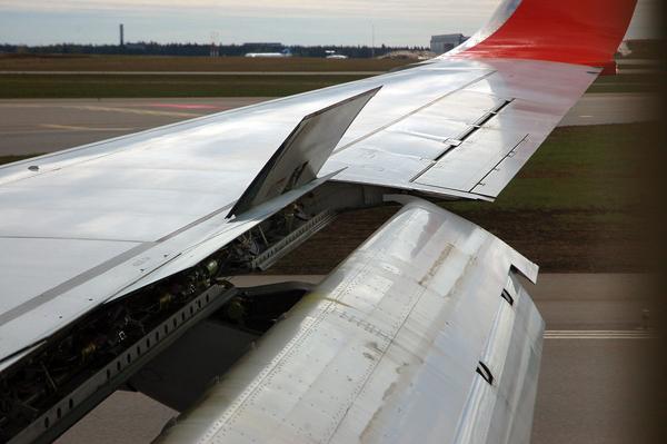
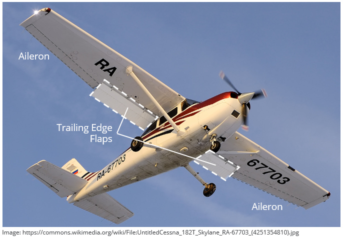
Flaps and slats work by increasing the camber of the wing through the mechanical actuation of leading-edge devices (slats) and trailing edge devices (flaps). Flaps generally span the inboard half of the wing and make up the last 25% – 30% of the wing chord. They are mechanically actuated and controlled by the pilot in the cockpit. The pilot can deploy the flaps to a number of predetermined angles below a certain speed; and does so before landing and often for a take-off as well.
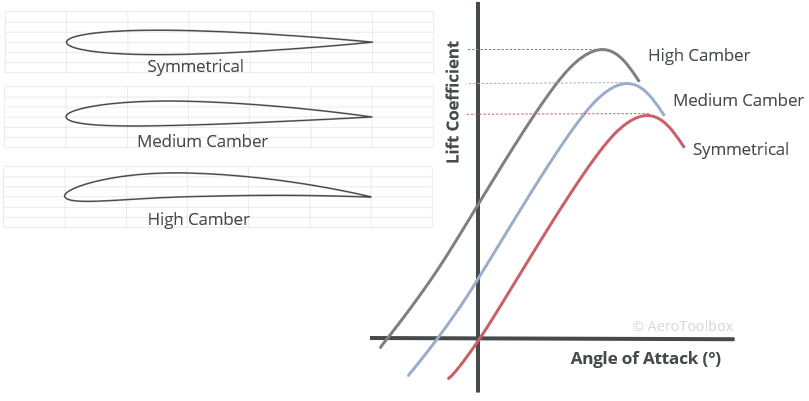
Camber is the measure of the curvature of the wing aerofoil profile. Aerofoils that are more highly cambered produce more lift at a given angle of attack. A deployed flap or slat works the same way and increases the camber of the wing, which produces more lift at a given angle of attack, or the same lift at a lower angle of attack.
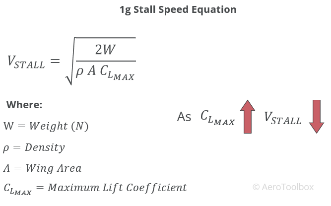
Increasing the lifting capability of the wing through the deployment of flaps increases the maximum lift coefficient of the wing. The lifting equation can be rearranged to solve for velocity, and the stall speed determined if the maximum lift coefficient is substituted into the equation. Increasing the maximum lift-coefficient by extending flaps reduces the stall speed of the aircraft, which is ideal during take-off and landing.
A typical graph of lift-coefficient against angle of attack for a light aircraft at three flap settings is shown below. The effect of adding flap during an approach and landing can be demonstrated by referring to the graph.
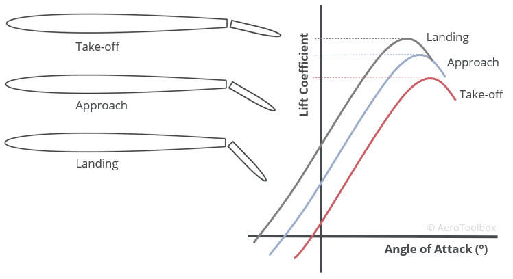
Each flap setting results in the aircraft operating on a different lift curve. Larger flap angles result in an increase in lift produced for a given angle of attack. This means that during the approach to land, adding flaps not only reduces the stall speed, but also reduces the angle of attack needed to maintain a given lift value. This results in a lower pitch attitude (more nose down) during the approach which gives the pilot better visibility during this critical phase of the flight.
Adding flaps not only increases the lift produced but also the drag. This is an important consideration which must be well understood when learning to fly. Increased drag can be useful when trying to slow the aircraft down to the approach speed but can present a problem when trying to climb away, for example during a go-around. You should always refer to your pilots operating handbook for the particular aircraft you are flying, and use the manufacturer recommended flap settings for take-off and landing. Large flap deployment angles also make the aircraft more susceptible to gusts. On windy days it is common in a light aircraft to fly the approach and landing at a reduced flap angle to improve control authority in these conditions.
Types of Trailing Edge Flaps
There are many variations of trailing edge flap in use on modern aircraft today. Plain or simple flaps merely deflect the trailing edge region downward to increase camber. More complicated multi-element designs make use of slots between flap sections to reenergise the airflow over the flap, delaying separation and increasing the lifting capability of the wing.
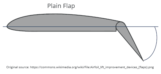
Plain Flap
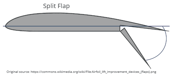
Split Flap
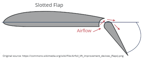
Slotted Flap
Slotted flaps are designed to extend downward in such a way so as to create a slot between the trailing edge of the parent aerofoil and the flap. This slot is carefully designed to allow higher pressure air from the lower surface to move through the slot, and to reenergise the airflow over the upper flap surface. This allows higher pressure air to flow over the upper flap surface, reducing the tendency for the air to separate. Slotted flaps provide greater lifting capability at steeper flap angles, reducing the stall speed of the aircraft further.
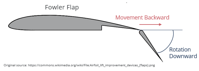
Fowler Flap
Referring to the lift formula, more lift can be produced either by increasing the lift coefficient (introducing camber through flaps), or by increasing the area of the wing. Fowler flaps do both; extending backwards and downwards to increase camber and wing area. Fowler flaps are the most effective flap systems in operation today but are more complicated to design, and heavier to implement. Fowler flaps can be combined with multiple slots to produce a slotted-fowler flap.
Leading Edge Slats
The principle of operation of a leading-edge slat is similar to a trailing edge flap. The camber of the aerofoil is increased by drooping the leading edge downward, and a slot or gap between the slat and the parent aerofoil allows the passage of air from the lower surface to the upper surface.
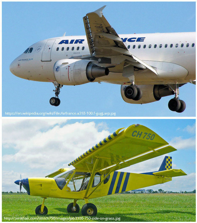
Slats are most often seen on larger jet airliners, but fixed slats have also found use on some STOL light aircraft where high lift is deemed more important that cruise performance. The permanence of a fixed slat creates additional drag at cruise when the additional lift generated by the slat is not required.
Properties of a High-lift System
We’ll close this post off with a short discussion of some important properties of a typical high-lift system, and how this should direct the way in which you use flaps in your light aircraft.
Design Trade-offs
It is important that a flap system is not only considered in terms of the additional lift being produced but also the additional drag that extending the flaps produces. Flap drag has two components: (1) the additional drag generated by the protrusion of the flap into the freestream, and (2) the additional lift-induced drag that is formed by trailing edge vortices shed off the edges of the flap.
The ratio of lift-to-drag is termed aerodynamic efficiency and is a measure of how much lift is produced relative to drag. The higher the ratio of lift-to-drag, the more efficient the aircraft and the lower the total drag signature. Extending flaps always reduces the aerodynamic efficiency of the aircraft. This means that the increase in lift that is produced is less than the additional drag that results. This is particularly important when discussing the use of flaps during a take-off where the aircraft is flying slowly, and any additional drag makes it difficult to climb out.
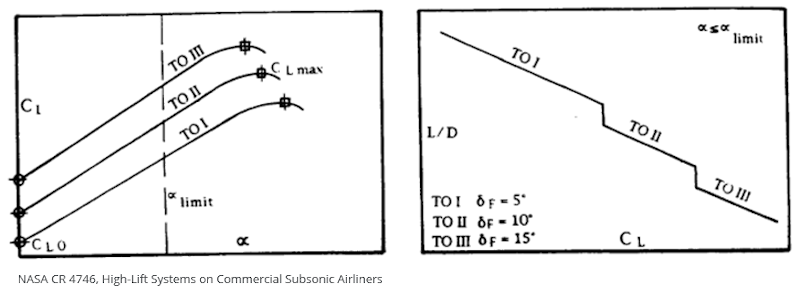
The example below shows the change in lift produced with angle of attack for three different flap settings (LHS) and the resulting aerodynamic efficiency of those flap settings (RHS). For all three flap settings, the additional lift generated by the increased flap angles reduce the overall aerodynamic efficiency of the aircraft.
Take-off Flap Settings
The flap setting used for take-off is very important as it will determine how the aircraft operates on the ground roll and the initial airborne segment.
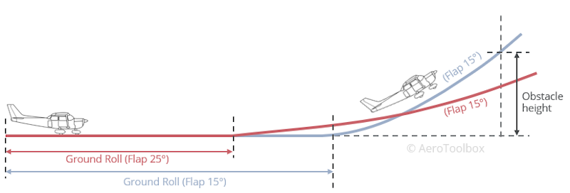
A take-off is defined as the horizontal distance covered from a stationary position on the runway to the point when the aircraft is airborne at a particular height above the ground (35 ft or 50 ft depending on the airworthiness regulations used). A take-off is therefore split into a ground roll and an airborne segment. Increasing the flap deflection angle used for take-off has the following effects on the two segments.
- Increasing the flap deflection angle reduces the stall speed which means that the aircraft can get airborne quicker, reducing the overall ground roll.
- The increased drag associated with the larger flap deflection angle reduces the aerodynamic efficiency, increasing the drag and making it more difficult to accelerate and climb out. This has the effect of increasing the airborne segment of the take-off.
It is very possible that an increased flap setting will therefore increase the total take-off distance. This could be a real problem if trying to get airborne from a short runway and clear a treeline at the end. It is important to always consult the pilot operating handbook and follow the advice given by the manufacturer with regards to selecting the most appropriate flap setting for a particular situation.
Thanks for reading. If you enjoyed this post or found it useful as a study aid, then please introduce your colleagues and friends to AeroToolbox.com and share this on your favorite social media platform.


