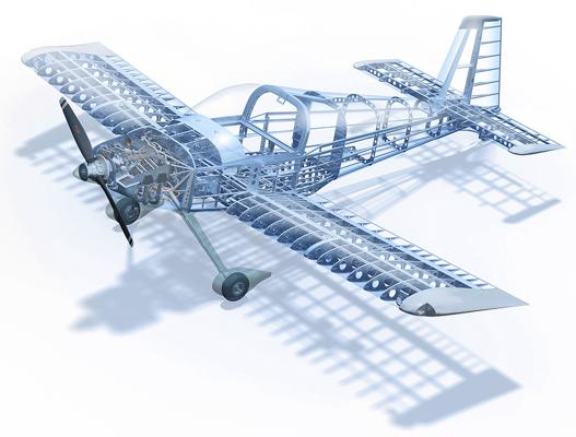
Welcome to part one in a five-part series on airframe structures and control surfaces. The aim of this mini-series is to provide an introduction to aircraft structures and the control surfaces attached to the wing and tail.
Part one is an overview and focuses on loads generation, structural design philosophies, and the material used in airframe manufacture.
Part two looks at the fuselage in more detail. We will discuss the various structural components that make up a typical fuselage design and discuss the types of loading that the fuselage must be designed to withstand.
Part three focuses on the structural design of a typical semi-monocoque wing, and the control surfaces attached to the wing.
Part four is dedicated to high-lift devices; namely the trailing edge flaps and leading edge slats common to modern aircraft.
Part five looks at the empennage, or tail section, and discusses the control surfaces found on the horizontal and vertical stabilizer.
We begin this series with a discussion of aircraft certification.
Aircraft Certification
The airworthiness of an aircraft design is signified through the awarding of a Type Certificate. This Type Certificate (TC) confirms that the aircraft is manufactured according to a design approved by the regulator, where that design ensures compliance with all airworthiness regulations.
Once a Type Certificate is issued the design is frozen and cannot be modified unless a further certification exercise is undertaken to cover the changes made to the design. Type Certificates are awarded through a regulatory body such as the Federal Aviation Administration (FAA) or the European Aviation Safety Agency (EASA). Most countries or regions have their own regulator who oversees the awarding a Type Certificate for operations in that particular region. In practice, most countries follow the directive of the FAA, EASA, or CAAC (Civil Aviation Administration of China) when awarding Type Certificates.
Using the FAA as an example, that administration publishes a set of airworthiness standards that provide a framework around which a new aircraft may be designed and ultimately certified against. Certification takes place not only for specific aircraft types but also engines and propellers. The four most applicable certification standards in terms of general or civil aviation are Part 23 and Part 25 for fixed wing aircraft and Part 27 and Part 29 for rotary wing aircraft.
CFR Part 23 - AIRWORTHINESS STANDARDS: NORMAL CATEGORY AIRPLANES
CFR Part 25 - AIRWORTHINESS STANDARDS: TRANSPORT CATEGORY AIRPLANES
CFR Part 27 - AIRWORTHINESS STANDARDS: NORMAL CATEGORY ROTORCRAFT
CFR Part 29 - AIRWORTHINESS STANDARDS: TRANSPORT CATEGORY ROTORCRAFT
Part 23 is applicable to normal category airplanes with a passenger seating capacity of 19 or fewer, and a maximum certificated take-off weight of 19 000 pounds or less. This covers almost all general aviation aircraft, and chances are that the light aircraft you are flying is certified under Part 23.
Light Sport Aircraft (LSA) are non-type certified which means that they are not necessarily designed to comply with all the regulations stipulated in Part 23. Certification not only covers the initial design and manufacture, but extends to maintenance, servicing, and repair. This adds a large overhead to the manufacturer (initial certification) and aircraft owner (purchase price and maintenance) which limits the potential market size for general aviation. The LSA category fills this void, allowing more people access to general aviation and aircraft ownership. This however does not mean that the FAA has no control over the design and manufacture of LSA’s. The aircraft are still designed to a standard agreed upon by the industry and endorsed by the FAA. Once the aircraft is complete, it is inspected by the FAA (or your country’s regulator), and an airworthiness certificate is issued which is valid so long as the required maintenance and inspections are kept up to date.
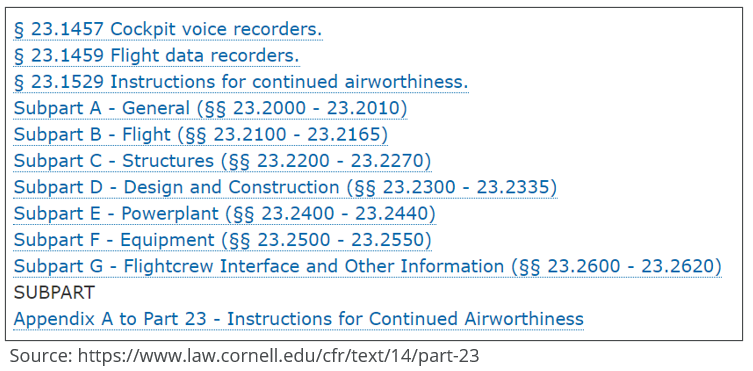
A snapshot of the highest-level breakdown of CFR Part 23 is shown below. The regulations are divided into several subparts which cover every aspect of design and operation including airframe structure (including design envelope and loading), propulsion, design and construction, and minimum demonstrated performance. An aircraft can only be awarded a Type Certificate if it is shown to comply to all aspects of the intended certification.
We will focus mainly on the areas of loads generation and airframe design philosophies in this airframe mini-series.
How are Loads Generated?
An aircraft’s structure is designed to withstand all possible combinations of loading within an envelope of operation defined in the applicable certification regulations. These structural design loads may originate externally or internally during operation, and consist of pressures, forces, and moments that occur while in flight, on the ground, or on water in the case of an amphibious aircraft.
Sources of Loading
An airplane in flight is subjected to forces and moments that are continuously changing as the aircraft moves through the air. The structure must be designed strong enough to withstand the worst combination of loadings that define the edges of the design envelope.
There are two primary forces that act on an airplane and several secondary forces that combine to form the flight envelope. The two primary sources of load are aerodynamic forces and inertial forces.
Aerodynamic Forces
Aerodynamic forces are generated as a result of the interaction between the aircraft and the atmosphere. The air in the atmosphere behaves like a fluid, with a density and viscosity. In the same way that a swimmer experiences opposition to his motion in a swimming pool, so an aircraft experiences an opposition, or drag force, as it flies through the air. Of course, the generation of lift (an aerodynamic force) is a fundamental requirement to remain airborne and so aerodynamic forces both oppose forward motion (drag) and provide the means to remain airborne (lift).
Aerodynamic forces can be broken down into two categories: pressure forces, which act normal to the airplane surface, and shear forces, which act tangent to the airplane surface.
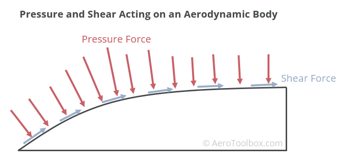
The lift generated by a wing is a good example of a pressure force; lift is generated due to the pressure distribution around the upper and lower surface of the wing. Wing-lift is not the only pressure force acting on an aircraft. The fuselage has its own pressure distribution defined by its shape, and pressure forces are generated at the horizontal and vertical stabilizer - especially when their control surfaces are deflected. Every external surface of the aircraft induces a pressure change in the air around the surface, and pressure forces exist wherever a pressure gradient exists.
It is often convenient for us to lump the resultant lift force produced by the wing at the center of pressure, but in reality that pressure force is distributed all across the wing, and each component of the wing structure must be designed to withstand the specific pressure forces acting on it throughout the design envelope. The same is true of every external surface of the aircraft.
Shear forces are responsible for aircraft profile drag. The air tends to stick to the aircraft surface as the airplane moves through the atmosphere. This viscous effect (air has viscosity in the same way that water or oil does) causes a drag force which opposes the direction of motion. The drag force acting on a wing tends to push the wing backwards, which induces stresses in the wing that must be reacted by the structure.

Inertial Forces
Newton’s laws tell us that a mass under acceleration experiences a force in the direction of the acceleration. The entire aircraft is subject to accelerations and decelerations during flight which impose inertial loads on the structure. The most obvious inertial load is that due to gravity which acts vertically downwards as weight; but there are many other inertial forces that must be considered across a typical design envelope.
The term inertia is used to describe the resistance of a body to a change in its velocity (acceleration). Remember that velocity is a vector and so refers to both magnitude (speed) and direction. When an aircraft enters a turn (changing direction), the force that causes the body to follow a curved path is termed the centripetal force and is directed inward to the center of the turn. The reaction to this force is felt in the cockpit as a centrifugal force which tends to push the pilot out of the turn. These inertial forces must be reacted by the aircraft structure during a manoeuvre and are most critical at the limits of the design envelope where the airplane will experience forces that may be many multiples of the aircraft weight.
When thinking about inertial forces it is important to consider how the mass is distributed through the aircraft. We often lump the entire aircraft mass at the center of gravity (c.g.) when drawing free-body diagrams to show the forces acting on the aircraft. In reality the mass is distributed throughout the aircraft and so an engine sitting on the wing can be thought of as its own mass, located some distance away from the aircraft c.g. This engine experiences its own inertial loading in a turn, and the structure that connects the engine to the wing must be made strong enough to withstand the local stresses induced in the turn.
A typical flight profile includes a take-off, climb, cruise, descent, and landing. This introduces a set of cyclical airframe loads which are broadly repeated each time the aircraft flies. Metal fatigue is a condition whereby a structural failure will occur below the static strength of the material due to tiny cracks that form as a result of repeated cyclical loadings. A fatigue analysis is an important component of an overall aircraft stress analysis.
Some other sources of loading are discussed below.
Thermal Forces
Temperature changes cause metal structure to expand (temperature increase) and contract (temperature decrease). This induces thermal stresses in the structure which must be considered throughout the aircraft’s operating temperature range. Local hot spots, for example at the exhaust point of an APU, are particularly susceptible to high thermal stresses.
Propulsion Forces
The thrust produced by a propeller and engine pulls (or pushes) the aircraft through the air and must be reacted by the engine mount structure and firewall. The engine is not run at a constant speed throughout a flight but is accelerated and decelerated as the power settings are adjusted. These thrust changes, along with any engine vibrations or shudders will introduce cyclical loads into the structure which must be accounted for through a fatigue analysis.
Pressurization
Pressurizing a cabin induces pressure loads into the fuselage structure which are opposed by the fuselage. Repeated pressurisation and depressurisation of the cabin leads to cyclical loading and potential fatigue concerns.
Landing Forces
The impact between an aircraft’s main wheels and the runway surface results in a large transfer of energy into the structure as the aircraft contacts the runway. Shock absorbers work to reduce the loading transferred; however, large point loads are still introduced at the attachment points. Regulations dictate that a hard landing load case be considered for both the main gear and the nosewheel.
Load Factor
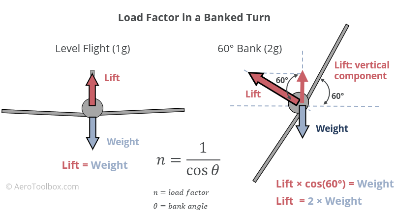
During a banked turn, the angle of the lift vector is no longer on the same line of action as the weight (which always acts vertically downward). This means that the wings need to produce additional lift in order that the component of lift acting in the direction of the weight is sufficient to balance the weight vector.
If the aircraft is banked at 60° in a level turn, the wing needs to produce a lift force twice the aircraft weight to remain level. A 60° bank angle therefore results in a load factor of two, and the aircraft is said to be sustaining a 2g turn (twice the gravitational force).
The load factor can be calculated using the formula shown in the image below.
The aircraft structure must be designed to withstand a certain load factor during normal operation, such that no permanent deformation or structural damage will occur when this load factor is reached. Design load factors are specified for different classes of aircraft and can be found in the airworthiness regulations. A typical light aircraft certified under Part 23 is certified to operate at a positive load factor of between 3 and 4 (limit load), and a negative load factor of between -0.5 and -1.5.
Gust Loading
The atmosphere is very seldom completely still and is usually characterized by turbulence, gusts, and other disturbances. These all contribute to the total loading on the aircraft, and very often a gust loading case forms a limiting point of the design envelope. It is important that the structure be designed to withstand a combined load case where a gust impacts the aircraft during a high-g manoeuvre in accordance with the relevant airworthiness regulation.
There may be certain manoeuvres that if completed above a particular speed would push the load factor above the maximum certified in the presence of a gust (turbulence). For this reason, aircraft have a maximum manoeuvring speed (VA) which is lower than the never exceed speed (VNE).
Limit and Ultimate Loading
The maximum manoeuvring load factor specified for a particular aircraft is known as that aircraft’s Limit Load. The limit load is defined as the maximum expected load that the aircraft will see during normal operation. A certified aircraft must be demonstrated to withstand a limit load with neither permanent deformation of the structure, nor any detrimental effects to the safe operation of the aircraft.
It is not sufficient to design an aircraft’s structure to only withstand a limit load with no additional margin of safety. Limit loads are always multiplied by a factor of safety to arrive at a set of ultimate loads that the structure must be strong enough to withstand. Ultimate loads may result in permanent deformation of the structure but must be shown to support that loading without total failure for at least three seconds. Typically, the limit loads are multiplied by a factor of 1.5 to arrive at the final set of ultimate loads.
Types of Loading
Moving from a global picture of loading, we now classify the specific types of loads that are introduced into the structural members of the airframe. There are four categories of loading that can be introduced into a structural member: axial, shear, bending, and torsion. Different types of structure (spars, stringers, skins etc) are designed to carry the different types of loads introduced during flight. That way the various airframe components work together to resist and distribute the applied loading.
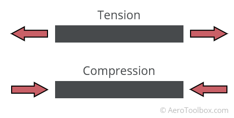
Axial Loading
An axial loading occurs when a force is introduced into a member in a direction normal to the member’s cross-section. This force is directed along that member’s line of axis and results in either tension (pulling apart) or compression (squeezing together) of the member.
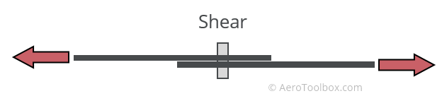
Shear
Shear loading occurs when a force is applied to the structure in the same plane as the cross-section of the member. Shear acts at right-angles to the axial loading and is created when two planes of an object try to slide past one another as may happen when a force is applied to two sheets riveted together.
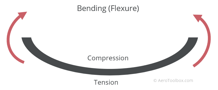
Bending
Bending loads (flexural loads) are introduced into the structure when an external load is applied perpendicular to the longitudinal axis of a member. Bending is seen in beams (eg main spar in a wing) as a result of the lift distribution along the wing, which tends to bend the wing upward under a positive g manoeuvre. In this instance the bottom section of the wing will be pulled into tension and the top of the wing will be compressed.
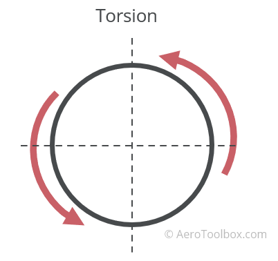
Torsion
Torsion loads are introduced into a structure as a result of a twisting due to an applied torque. An example of a torsion load on an aircraft is the response of the fuselage when the rudder pedal is fully deflected. This force generated at the rudder will tend to twist the fuselage due to the moment arm between the center of pressure of the rudder and the neutral axis of the fuselage. The torque of a propeller also introduces a torsional load into the aircraft structure.
Airframe Design Philosophies
There are three common design philosophies associated with the structural layout of a typical aircraft. The most common design philosophy in use today is the semi-monocoque design, which evolved from the earlier truss and monocoque designs.
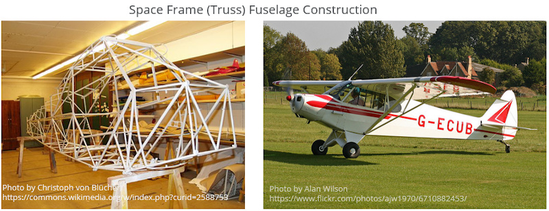
Space Frame (Truss)
The earliest aircraft structures were built with a space frame or truss construction. Before the Second World War it was common to use wood as the primary structural material, with a fabric covering stretched over to provide the aerodynamic shape. Later truss structures were built from steel tubing like that seen on the Piper PA-18 Cub fuselage. A truss structure is a simple but inherently inefficient design, as the aerodynamic covering contributes mass but provides no real stiffness to the design. All the load is therefore carried in the truss members.
Monocoque
A monocoque structure is a single-shell design where the skins that make up the shell carry all the loading and contribute all the structural rigidity to the design. This can result in a light structure if properly designed, as no substructure is required to support the load-bearing skins. There are however two major downsides to a monocoque structure. The first is that the skin must be designed with very intricate curves and shapes to avoid buckling of the skin under loading. This requires a complicated and expensive manufacturing process to complete. The second is the difficulty in the incorporation and distribution of point loads into the structure. Typical point loads introduced into an airframe structure are those generated at engine mountings or the landing gear attachment points. Monocoque designs have largely been replaced by semi-monocoque structures as steel was replaced by aluminium as the primary airframe material.
Semi-monocoque
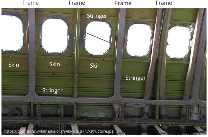
A semi-monocoque structure is far and away the most common airframe construction method employed today. The design philosophy sits somewhere in between a pure monocoque (skin takes all the load) and a truss structure (all load taken by the space frame) where both the skin and sub-structure are load bearing and contribute to the overall stiffness of the structure.
A typical semi-monocoque structure consists of longitudinal members (stringers, longerons, spars), which carry bending and support the skin against buckling, transverse members (frames, ribs) which carry transverse shear and provide a means for point load introduction, and skins which carry in-plane shear loads and introduce that load into the substructure. All structural members in a semi-monocoque structure work together to resist deformation and to transfer the applied loading.
Airframe Materials
Modern aircraft are predominantly built from aluminium or a carbon fibre composite. A traditional light aircraft, such as the Piper PA-28 or Cessna 172, follows a semi-monocoque design philosophy and is manufactured from aerospace grade aluminium. Newer aircraft like those in the Cirrus family or the Boeing 787 are built predominantly from carbon fibre. We’ll end this first tutorial by introducing these two materials now.
Aluminium
Aluminium alloys have the predominant airframe material since the 1920’s and 1930’s and the dawn of the Second World War. The use of aluminium also coincided with a move away from truss-like wooden structures with fabric covering to the modern semi-monocoque designs that we know today.
Aluminium is an ideal material for use in the manufacture of airframe structure. It may not be as strong or stiff as steel, but it is considerably lighter, which means that thicker aluminium sections can be used without an increase in the overall structural mass. A thicker aluminium structure is better able to resist buckling than an equivalent thin steel structure of equal mass. This is an important consideration in the design of a semi-monocoque structure, where an aluminium sheet can withstand a buckling load almost eight times greater than a steel plate of equal mass.
Aluminium airframes are easier to repair than a composite structure and external damage is relatively easy to identify. This is in contrast to composites where damage is often internal and not visible from the surface.
Composites
A composite used in aircraft manufacture generally consists of two primary materials. Layers of carbon or glass fibre are laid up between layers of resin (matrix), which glue the material together and give the composite its shape. The fibres are the primary load-carrying material, and so the composite is very strong in the fibre direction. The matrix provides through-thickness strength. A composite sandwich is a popular design where two thin carbon fibre skins are laid up between a honeycomb material, giving the structure both in-plane and out-of-plane strength.
Whereas an aluminium billet is equally strong in all directions, a carbon fibre material’s primary load carrying capabilities are in the direction of the fibres. This is both an advantage, and a disadvantage. The composite layup can be tailored to a specific load path, which means that a lighter structure can be designed if the load path is well understood. If the actual loading deviates from that designed against, and the load path varies, the material may be too weak to sustain the loads through it. Composite parts are usually made up of a combination of 0°, 45°, and 90° carbon fibre layers to provide strength in all principle directions.
Carbon fibre is usually preferred to glass in aircraft design as it has a higher bending stiffness and is also much lighter. Carbon fibres are more brittle than glass which results in a material with relatively poor impact resistance. Regions on the aircraft that are subjected to impacts, such as the leading edge of the wing, are often laid up with layers of glass over the carbon to provide the necessary impact protection.
The two primary advantages of a carbon composite over the more traditional aluminium construction are a lighter structure (can be up to 30% lighter if well designed), and a much smoother finish with complex curvatures, tailored to minimise drag. This can provide a performance improvement over traditional aluminium aircraft of a similar design.
Carbon structure is more difficult to manufacture than aluminium as in effect you are building both the structure and the material simultaneously. Inspections and repairs of the composite are also more difficult to complete as damages to the composite often occur inside the material layup, which is not visible to the human eye.
It would appear that composite materials represent the future of aerostructure manufacturing, especially on larger airliners, where the mass benefits of a composite airframe outweigh both the additional costs incurred during manufacture, and the more challenging inspections and repairs during the life of the aircraft.
This brings us to the end of the first tutorial in our mini-series on airframe structure. If you enjoyed this post or found it useful as a study aid, then please introduce your colleagues and friends to AeroToolbox.com and share this on your favourite social media platform. Thanks for reading.


