The question of how an airplane’s wing produces the lift required to fly is one of the most frequently asked questions by new pilots and in my opinion, unfortunately one of the most poorly answered.
This was my experience when learning to fly. I remember opening a prescribed principles of flight textbook and as I read through the section dealing with how a wing generates lift I started to shake my head. As an aeronautical engineer I believe that it is important that sound physics principles are taught to new pilots; not because I wish to be overly pedantic, but because I believe that a solid grounding in the physics of flight may just save you one day if you’re ever faced with an in-flight emergency.
There is nothing more critical in flight then ensuring that your aircraft is generating sufficient lift to remain controllable. There have been countless stall-spin accidents over the years, many due to a poor understanding of the generation of lift, the onset of stall, and the resultant forces acting on an airplane during a turn. We’ll cover all these topics over the course of the next few weeks but for now let’s start with how a wing actually generates lift.
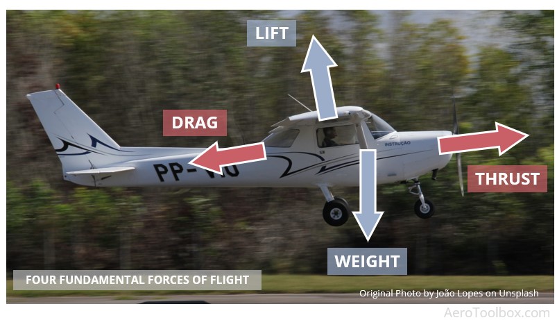
Fundamental Forces Acting on an Airplane
In a previous article we covered the four fundamental forces of flight where we showed that a lifting force is required to counteract the weight of the aircraft. This force is primarily produced by the wing and acts at the wing’s center of pressure. The lift force acts perpendicular to the direction of flight and must act behind the aircraft’s center of gravity to ensure a stable configuration.
Lift is a Pressure Phenomenon
From the onset it is useful to state that the generation of lift by a wing is a pressure phenomenon caused by the resulting pressure field induced by the upper and lower surface curvatures of the airfoil.
We’ll spend the rest of this article digging into a little more detail as to how and why curvature induces a lifting force, but the takeaway is clear: lift is a pressure phenomenon.
We’ll make use of three physics principles in our discussion: Newton’s Laws of Motion, forces generated by a curved path, and Bernoulli’s equation relating pressure and velocity. Hopefully we’ll be able to correct a few misconceptions as to how these should be applied as we go.
The Physics at Play
Newton's Laws
The first instalment in this series on the Principles of Flight focused on Newton's Laws of Motion and how these should be used to relate mass, force, and acceleration.
Newton’s Second Law shows that a resultant force is required in order for a body to accelerate. The direction of acceleration of the body is always in the direction of the applied force. This is written mathematically as:
$$ F = m \times a $$
Bernoulli's Equation
Bernoulli’s equation is often cited as a means to explain the generation of lift. The equation is actually only valid in incompressible flow (speeds below M0.3) and relates the pressure and velocity of two points along a streamline.
$$ P_{1} + \frac{1}{2} \rho V_{1}^{2} + \rho g h_{1} = P_{2} + \frac{1}{2} \rho V_{2}^{2} + \rho g h_{2}$$
A classic application of the equation is the flow through a venturi. The pressure drops in the venturi throat with a corresponding increase in velocity.
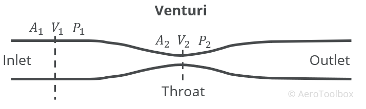
For the full derivation of Bernoulli’s equation and how it relates to the flow through a venturi, please see our article on the workings of an aircraft carburetor.
The argument is often made that the upper surface of a wing looks somewhat like one side of the venturi. This surface is then placed in the flow field and the resulting velocity increase near the surface and corresponding pressure drop is explained through Bernoulli’s equation.
There are two problems associated with this explanation:
- Bernoulli's equation is only valid along a streamline and so is not strictly applicable to the entire flow field where there is no explicit relationship between the pressure and velocity of neighbouring streamlines.
- This depiction of lift based solely on Bernoulli’s equation does not take into account the effects of the lower surface of the wing, nor does it describe the effect that angle of attack has on the total lift generation.
Bernoulli’s equation (which is really just a mathematical representation of Newton’s Second Law applied to a streamline) does have a part to play in explaining the generation of lift, but it doesn’t tell the whole story.
Streamlines and the Flow Field
When describing the flow of air around an object it is often helpful to trace the path that particles in that flow field travel. A streamline is simply a particle trace that shows the direction that a steady stream of particles travel in with respect to time. The tangent vectors associated with a streamline gives the velocity field of the flow.
A collection of streamlines in the vicinity of a body situated in a free stream of air provides an intuitive description of the flow around that body. In the case of a wing, a plot of streamlines around an airfoil section at a positive angle of attack shows clearly how the shape of the airfoil influences and deflects the fluid particles, causing a change in the flow field. 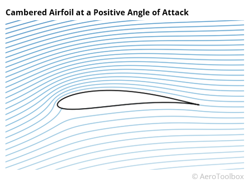
It is this deflection or curvature of the streamlines that we are most interested in as this is what is responsible for the pressure changes around the airfoil and subsequent generation of lift.
Straight Line Flow
Let’s start by applying Newton's Second Law to particles travelling along a straight streamline. To do so we must account for all the forces acting on a single parcel of air. We can then determine the direction of the net force which leads to the acceleration, and finally the velocity.
When talking about a parcel of air we are really just grouping a number of individual air molecules together and treating them as single unit with a mass equal to the sum of the individual molecule masses.
We’ll make a number of assumptions to simplify the model; namely that we can neglect the contribution of all forces acting on the parcel except for pressure. The pressure force dominates the flow field so this is a valid assumption.
The only other notable force to consider is friction; this has a direct impact on the boundary layer of the flow, and is very important when discussing the drag force, but can be neglected when discussing lift. Finally, we limit ourselves to conditions of steady flow. This means that the overall flow field does not change very quickly with time.
Let’s take our parcel of air and assume that there is a pressure gradient acting over it such that the pressure ahead of the parcel is lower than the pressure behind it. This pressure gradient will induce a force that will push the parcel forward along the streamline.
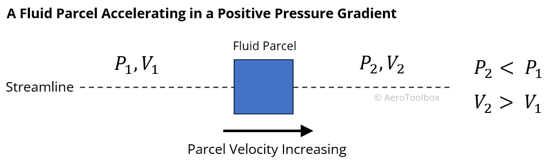 From Newton’s Second Law this force results in the parcel accelerating along the streamline such that its velocity increases in the direction of the flow. If the pressure field were reversed, then the parcel would decelerate as it moves in the flow field.
From this example we can conclude that decreasing pressure in the direction of flow causes the air to accelerate in that direction.
Here is where Bernoulli’s equation can be applied to all points along a streamline; an increase in velocity (particles accelerating) results in a drop in pressure and vice versa.
Flow Along Curved Surfaces
Things get a little more complicated when we introduce curvature into the picture. Intuitively air will bend to conform to the shape of a body placed in its path. In the case of a wing, the curved upper surface and flatter lower surface of a conventional airfoil causes the air to split at the leading edge and follow the two surface contours.
Here’s where the greatest misconception around the generation of lift is perpetuated.
The individual parcels of air splitting at the leading edge do not have to meet again at the trailing edge.
The notion that the air flowing over the upper surface has further to travel and therefore must do so at a greater velocity thereby dropping the pressure is completely false and should be dropped from all explanations of lift. This has been thoroughly debunked by Cambridge Professor Holger Babinsky with a simple wind tunnel experiment where smoke is pulsed over an aerofoil and the resulting flow captured.
To understand why the pressure on the upper surface drops we need to briefly discuss the physics behind what occurs when parcels of air are forced to change direction in the flow.
In order for a parcel of air to change direction (follow a curved path) there must exist a centripetal force that acts normal to the direction of flow.
To visualise this, you can think of swinging a ball connected to a string above your head. The string is required to keep the ball tethered and to stop it flying away. The centripetal force is the reaction to this force.
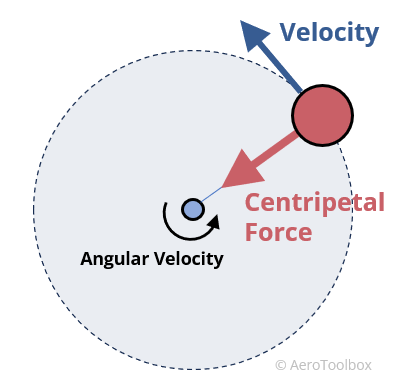
In the case of air following a curved path around a wing, this centripetal force must be generated as a result of a pressure difference in the direction of the force (Newton II). This implies a pressure difference across the streamline (transverse pressure gradient), in contrast to the example of flow in a straight line where the force was only in the direction of motion.
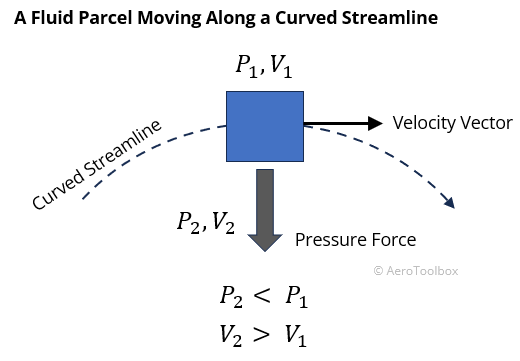
If a streamline is curved, the pressure must decrease in the direction of the centre of curvature.
The Flow Field Around an Airfoil
We now have everything we need to put together an explanation for how an airfoil generates lift.
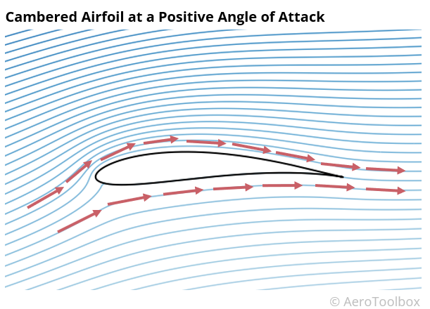
The image below of the flow field around a conventional general aviation type airfoil has been computed using a potential flow panel method and clearly shows the curvatures of the various streamlines induced by the airfoil shape. In our example, the wing is inclined at a positive angle of attack, similar to what one would see during a climb.
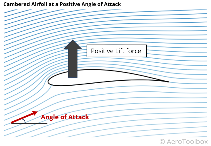 There is a clear difference in the curvature of the streamlines above and below the airfoil, and we can use what we have just learnt to map the pressures above and below. From there we can estimate the net force induced by the presence of the aerofoil in the freestream.
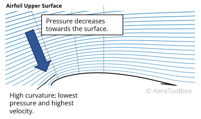
Upper Surface
The curvature on the upper surface is more pronounced than on the lower surface and the direction of curvature is such that the pressure drops as one moves closer to the surface. This results in a region of low pressure above the upper surface of the wing which sucks the wing upward and produces a lifting force.
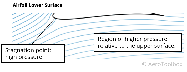
Lower Surface
Here there is a mix of curvatures such that we would see regions of relative higher pressure and relative lower pressure on the underside of the wing. Here we can conclude that the lower surface of this aerofoil does not contribute as much as the upper surface to the generation of lift as the upper surface.
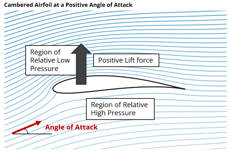
Net Force
In this example of a conventional airfoil at a positive angle of attack there is a relative low pressure on the upper surface so that the net force is upward and positive lift is generated.
A Symmetrical Airfoil can Produce Lift Too
A symmetrical airfoil is one where the curvature on the upper and lower surface is identical. In the case where the aircraft is flying at zero angle of attack the resulting flow field on the upper and lower surfaces will be identical. Thus, any drop in pressure on the upper surface is counteracted by an equal and opposite pressure drop on the lower surface.
A symmetrical airfoil at zero angle of attack therefore produces no net vertical force and zero lift is produced.
The curvature of the airfoil may be identical on the upper and lower surface, but increasing or decreasing the angle of attack of the wing will cause a relative change in the streamline curvatures above and below the wing.
A set of streamlines around a symmetrical airfoil at a positive angle of attack is shown below. The relative angle of the upper surface causes increased flow curvature on the upper wing surface with a resulting region of low pressure (suction). This results in a positive net lifting force and the wing is able to produce upward lift.
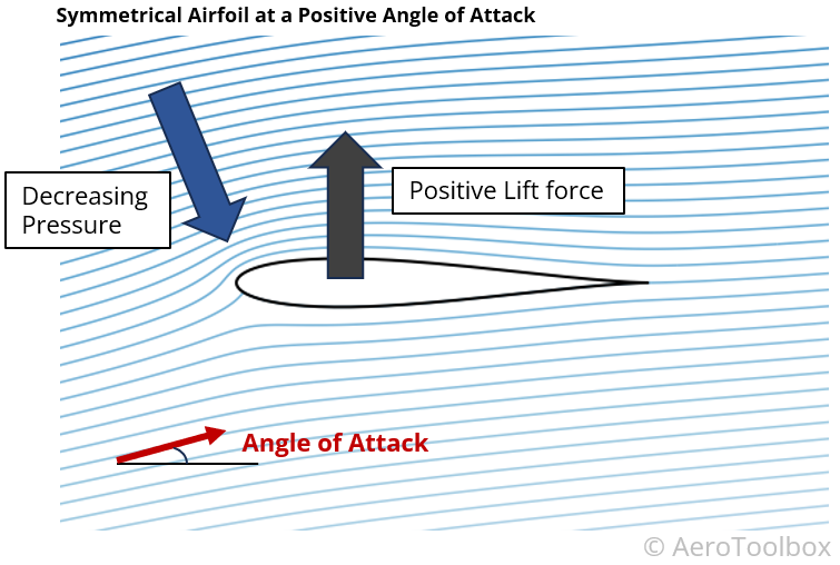 A symmetric aerofoil at a negative angle of attack would produce a net downforce as the lower pressure region would now be seen on the lower surface.
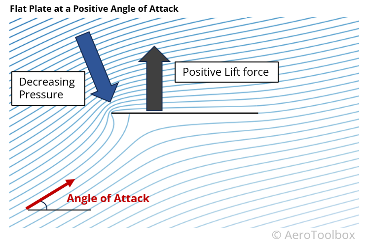
Lift Produced by a Flat Plate
If you have ever stuck your hand out of the window of a moving car you will have felt your hand being pushed upward. A flat plate at a positive angle of attack can also produce a lifting force. In this case there is no surface curvature, but the angle of attack induces a flow curvature which results in a pressure drop on the upper surface.
The flow field around a flat plate at a positive angle of attack is shown below; this has been generated using computational methods that ignore flow separation and so while not strictly accurate, (the high angle of attack is sufficient so as to induce flow separation and stall on the upper surface) still provides an insight into the effect of angle of attack on the net lift produced.
Wrapping Up
The physics behind how a wing produces lift is one that often perplexes students and many explanations designed to simplify the underlying physics fall short, leading to some large misperceptions of the way a wing works.
Lift is generated when curvature is introduced into the flow field by the interaction of the air with the wing’s airfoil section. This streamline curvature requires the existence of a transverse pressure gradient which results in a region of low pressure on the upper surface of the wing. This low pressure interacts with the relatively higher pressure on the underside of the wing to generate a net upward force that we call lift.
The pressure and force are related through Newton’s Laws of Motion, principally Newton’s Second Law, which describes how the changing velocity of the air leads to the existence of a force in the same direction.
Bernoulli’s equation is actually only valid along a single streamline and is useful to relate the increasing velocity along a streamline to the corresponding drop in pressure that causes suction and lift.


