Have you checked out our new Carburetor Icing Probability calculator yet?
The carburetor forms a part of the engine’s induction system and is responsible for bringing together and mixing the air and fuel. This mixture is then routed to each cylinder where it is ignited as part of the four-stroke engine cycle.
The carburetor is still the most commonly used device in light aircraft to atomize and mix the fuel and air required for combustion. The alternative is a fuel injection system. Fuel injected engines use a pump and a fuel distribution system to inject fuel directly into the induction system through a set of fuel injectors. Fuel injection has largely replaced carburation in the automotive industry but not so in the engines of light piston aircraft.
The Carburetor
A carburetor (or carburettor) is a mechanical device that makes use of the principle of a venturi to atomize liquid fuel and mix it with air in the correct ratio for optimum combustion. This mixture is then sent to the engine intake manifold where it is combusted.
Physics of a Venturi
A venturi is a simple device that makes use of two physics principles: the conservation of mass and Bernoulli’s equation to define the relationship between velocity, pressure, and area through a constricting and expanding tube through which air travels.
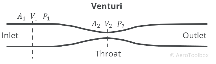
The conservation of mass states that mass cannot be created or destroyed, which means that the mass in a closed system must remain constant. This can be written between any two points in the venturi as:
$$ \rho_{1}A_{1}V_{1} = \rho_{2}A_{2}V_{2} $$
Assuming that air is incompressible (this is a valid assumption at speeds below Mach 0.3), the air density remains constant through the venturi and so the density term can be removed from both sides of the equation.
$$ A_{1}V_{1} = A_{2}V_{2} $$
The velocity in the throat of the venturi is therefore a function of the area ratio. Since \( A_{1} > A_{2} \) this means that the velocity in the throat of the venturi is greater than at the inlet.
$$ V_{2} = \frac{A_{1}}{A_{2}} $$
Bernoulli’s equation is valid for incompressible flow between any two locations along the venturi and allows us to relate the pressure difference between the inlet and the throat to the resulting velocity difference. The continuity equation shows us that \( V_{2} > V_{1} \), and now we can rearrange the Bernoulli equation, and show that the pressure at the throat drops as the velocity at the throat increases.
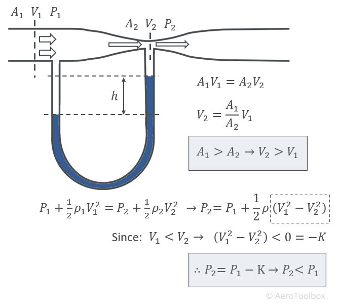
The conclusions that can be drawn from the venturi analysis are:
- The velocity at the throat increases relative to the inlet.
- The pressure at the throat decreases relative to the inlet.
The carburetor makes use of this velocity increase and corresponding pressure drop at the venturi throat to suck fuel into the airstream where it mixes with the intake air.
Carburetor Design and Operation
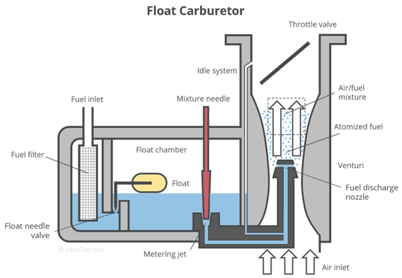
The most common carburetor type found on light aircraft is the float carburetor, named for the float used in the fuel chamber to regulate the fuel level. A schematic of a typical float carburetor is shown below.

Float Chamber
The carburetor is divided into two separate regions: the fuel chamber and the venturi. Fuel enters the fuel chamber via the fuel system where a float regulates the level in the chamber. This float works the same way as the float in a typical toilet cistern. The buoyant part of the float will always float on the surface of the liquid fuel. The float is connected to a linkage system which terminates in a needle valve. As the fuel level in the float chamber rises or falls, the float moves with the fuel level, opening or closing the valve. This regulates the total fuel present in the chamber and keeps the fuel level almost constant during engine operation. The float is designed to keep the level of the fuel in the chamber below the level of the fuel discharge nozzle. The fuel level needs to remain below the nozzle to ensure that no fuel leaks from the carburetor when the engine is not running.
Discharge Nozzle
Passageways between the float chamber and the venturi section of the carburetor provide a passage for liquid fuel to be sucked from the chamber to the discharge nozzle as intake air is accelerated by the venturi action. The chamber is vented and so always remains at the ambient atmospheric pressure. Air entering the inlet of the venturi sees a velocity increase with a corresponding pressure drop at the venturi throat. The discharge nozzle is positioned in the throat where the pressure is the lowest. This establishes a pressure gradient between the float chamber (atmospheric pressure) and the discharge nozzle (pressure less than atmospheric) , which results in fuel being sucked out the chamber, though the metering jet, and into the venturi stream at the discharge nozzle.
Metering Jet
The metering jet is an orifice (a threaded valve with a hole through the middle) where the diameter of the orifice determines the maximum fuel flow rate from the float chamber to the discharge nozzle. Running the engine at wide open throttle without a metering jet would result in too great a fuel flow rate for the engine to efficiently consume. The orifice limits this to the maximum desired fuel flow rate.
The velocity increase at the throat venturi combined with the geometry of the diffuser results in the fuel instantly atomizing (breaking up of the fluid into droplets). The atomized fuel is then mixed with the incoming air, routed through the engine intake manifold and onto the combustion chambers where it is ignited.
Air Bleed
The pressure differential between the float chamber and the venturi throat is referred to as the metering force. The metering force increases as the throttle is opened due to the increased mass flow (rate of air flow) through the venturi. At lower throttle settings the metering force reduces and may not be able to supply the engine with sufficient fuel. This necessitates the inclusion of an air bleed in the diffuser nozzle to assist in vaporizing the fuel and providing a more even fuel discharge through the full range of throttle settings.
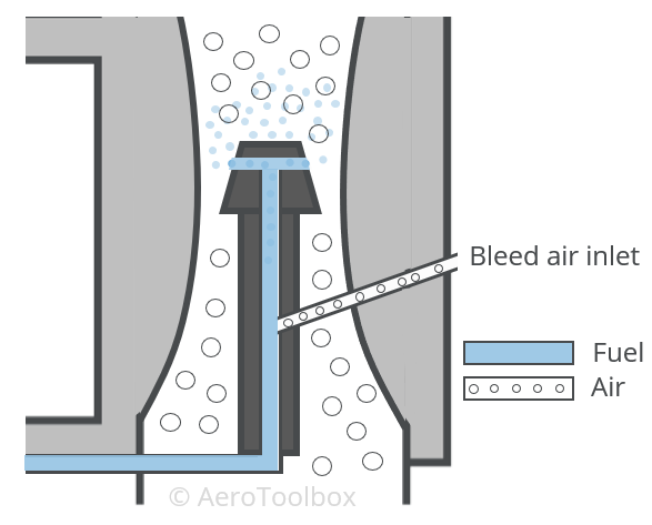
The air bleed draws in air from a region in the carburetor where the air is at or close to atmospheric pressure, and mixes this with the fuel being sucked into the diffuser by the action of the venturi. The addition of air into the diffuser nozzle reduces the density of the fuel and destroys the surface tension of the liquid fuel molecules. This makes the fuel less likely to stick to the side of the nozzle, and more likely to mix with the air and vaporize, especially at lower throttle settings.
Engine Throttle
The volume of air-fuel mixture entering the intake manifold and the ratio of air-to-fuel in this mixture are controlled by the throttle and the mixture control levers respectively.
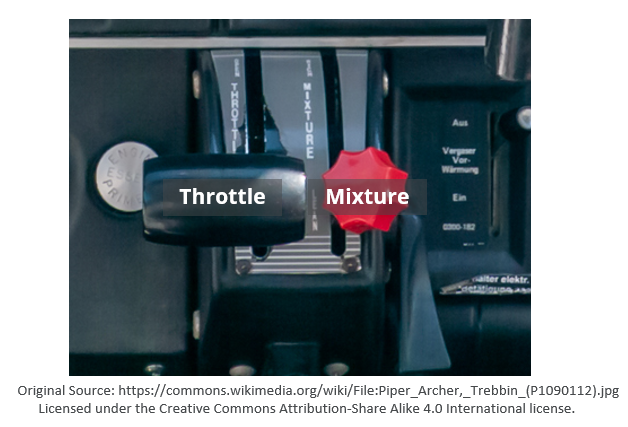
The throttle and mixture control levers are situated in the cockpit and give the pilot direct control over the power output (throttle) and the air-fuel ratio (mixture).
The throttle lever operates the butterfly valve situated in the venturi portion of the carburetor. As the throttle is opened, the valve opens which allows a greater volume of air-fuel to enter the combustion chambers of the engine. In an aircraft with fixed pitch propeller opening the throttle results in the rpm of the propeller increasing and a corresponding increase in thrust. If the propeller speed is governed (constant speed propeller) then opening the throttle will result in an increase in manifold pressure while the propeller speed remains the same.
Closing the throttle results in the butterfly valve closing, which limits the volume of air-fuel mixture that the engine receives. When the throttle is in the fully closed (idle) position the flow rate through the venturi may be so low that the engine is unable to idle without intervention. The low flow rate of air through the venturi limits the pressure drop at the throat, which in turn limits the suction of fuel from the float chamber to the discharge nozzle.
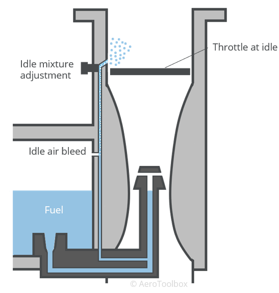
Idle Passage
An idle passage is incorporated into the carburetor to allow the engine to idle. This is a passageway which bypasses the venturi and provides a path for the fuel to flow directly from the float chamber to the low-pressure side of the throttle valve. Closing the throttle valve creates a region of high pressure on the venturi side of the valve. The pressure on the engine side of the throttle valve is lower due to the suction action of the pistons. This low pressure sucks the fuel through the idle bypass and into the engine. A bleed air passageway is built into the idling system to allow air and fuel to atomize and mix before entering the engine intake manifold.
When the throttle is opened, the pressure drop at the diffusing nozzle is once again sufficiently strong to suck fuel through the main diffuser. This restores the normal operation of the carburetor, and no fuel passes through the idling system.
Mixture Control
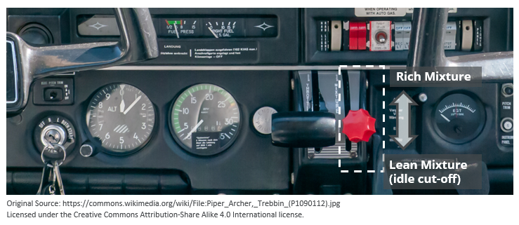
The ratio of fuel-to-air that enters the engine manifold is termed the mixture and is controlled via a lever in the cockpit. Mixture levers are almost always painted red in color and are usually placed to the right of the throttle lever.
Advancing the mixture lever forward allows more fuel to enter the discharge nozzle in the carburetor venturi, increasing the ratio of fuel-to-air. This is termed enriching the mixture. Pulling the mixture lever backward allows less fuel to enter the venturi, decreasing or leaning the mixture. Pulling the mixture lever all the way backward (or out on plunger type mixture levers) results in a situation where no fuel is discharged into the venturi. With no fuel entering the engine ignition is no longer possible, the engine stops, and the mixture is said to be at idle cut-off.
Mixture Control Systems
The mixture lever in the cockpit is connected to the carburetor and controls the amount of fuel allowed to pass through the metering jet. There are two carburetor mixture control systems primarily seen in light aircraft: the needle type control and the back-suction control.
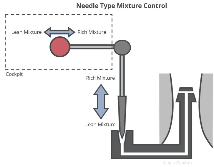
Needle Type
The needle type mixture control consists of a needle valve situated at the metering jet which is connected to the mixture lever in the cockpit. As the mixture is enriched (lever moved forward), the needle valve moves away from the metering jet orifice, allowing more fuel to pass through to the diffusor nozzle. Conversely, leaning the mixture out causes the needle valve to seat more closely to the jet orifice which reduces the flow of fuel into the venturi. If the mixture lever is closed to idle cut off (ICO) the valve seats completely into the orifice, cutting off fuel supply to the engine.
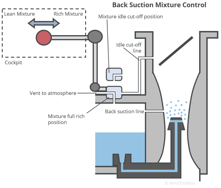
Back Suction Control
Back-suction control is another widely used method to control the rate of fuel flow into the venturi. Flow control is achieved by varying the pressure differential between the venturi and the float chamber through a control valve and a back-suction line which connects the float chamber to the venturi.
With the mixture lever at full rich, the valve connects the float chamber to a line which is open to the atmosphere. This provides the maximum pressure differential between the chamber and venturi and results in the greatest fuel flow into the diffuser.
As the mixture control is progressively leaned, the valve to atmosphere closes and the pressure in the float chamber drops as a result of air drawn in through the passage between the chamber and the venturi. A drop in chamber pressure results in a smaller pressure differential between the chamber and venturi, which limits the fuel flow rate, thereby leaning the mixture.
When the mixture lever is brought all the way back to idle cut-off, the control valve is completely closed to atmosphere, and rather open to an idle cut-off passageway which connects the float chamber to the low-pressure side of the engine. This causes a pressure drop in the chamber greater than the drop across the venturi, effectively sealing the fuel in the chamber and cutting supply to the engine.
Accelerating System
A rapid opening of the throttle from a lower power setting to a high setting results in a large volume of air rapidly entering the venturi as the throttle valve is opened. The fuel dispensing system in the carburetor reacts to the throttle change more slowly than the air through the intake, resulting in a short period where the fuel-air ratio drops. This temporarily leans the mixture and can cause the engine to respond slowly to the throttle change, or even “stutter” due to a lack of fuel in the mixture. One method of overcoming this is through a small piston pump in the carburetor which injects additional fuel into the venturi. This temporarily enriches the mixture until the metering system is able to catch up.
Economizer
The economizer is a needle valve which opens at higher power settings to allow additional fuel to bypass the main metering jet and enter the discharge nozzle directly. This has the effect of enriching the mixture, which is necessary at high power settings to aid in the cooling of the cylinders and to help avoid detonation.
Effect of Altitude on Mixture Settings
Mixture ratios are specified in terms of the ratio of the mass of fuel to the mass of air and not by volume. The energy released by igniting an optimum mixture of fuel and air is termed the calorific value of the fuel and is usually specified as a function of the mass of the fuel.
The specific energy of the fuel is the amount of energy released by the fuel per unit mass of fuel. This assumes that the fuel is perfectly combusted in air and none of the fuel remains after combustion. Typical values of the specific energy of Avgas 100LL, Jet-A, and Jet-A1 are shown in the table below.
| Fuel | Specific Energy (MJ/kg) |
|---|---|
| Avgas 100LL | 43.5 |
| Jet-A | 43.0 |
| Jet-A1 | 42.8 |
The specific energy values shown above will only be reached if the fuel-air mixture entering the combustion chamber is such that no unburnt fuel will remain after combustion. This would occur at an optimum mixture ratio.
This ratio has been determined by test to be around 1:15. That is, 1 part of fuel to 15 parts air (by mass).
Air becomes less dense at increased temperatures and at higher altitudes. This has a direct effect on the mass of air entering the engine intake. In order to therefore maintain the optimum mixture ratio, the pilot must incrementally lean the mixture as the aircraft climbs and enrich the mixture as the aircraft descends to compensate for the changing mass of air entering the engine.
Best Power
The best power mixture is simply the mixture setting that will allow the engine to produce the maximum power. This mixture settings lies somewhere between 1:11.5 and 1:15.
Best Economy
The best economy mixture setting will maximize the ratio of power produced to fuel burnt.
$$ \frac{Power \ Produced}{Fuel \ Consumption} = Maximum $$
This occurs at a mixture setting between 1:15.5 and 1:18. These mixture settings are leaner than the best power setting (less fuel per mass of air) and so do not produce as much power as the richer best power setting; however, this is offset by the improved fuel consumption.
Leaning the Mixture
The optimum mixture setting can be achieved by referring to the exhaust gas temperature (EGT) gauge in the cockpit. The temperature at which the exhaust leaves the engine provides a good indication as to the efficiency of the combustion. Richer mixtures produce cooler exhaust gas temperatures as the unburnt fuel aids in cooling the engine.
As the mixture is leaned, the exhaust gas temperature will rise to a maximum before a noticeable drop-off is seen. The peak EGT (corresponding to the most efficient point) is always seen at the same fuel-air ratio (mixture setting) but will occur at a different mixture lever position as the density of air varies with temperature and altitude.
The method to set the optimum mixture involves leaning the mixture until the EGT reaches a maximum value, and then enriching slightly to reduce the temperature in accordance with the flight manual. Refer to your aircraft flight manual for specific details around exactly how to lean the mixture for best power or best economy settings.
Spark Plug Fouling
Running the engine at too rich a mixture can result in excessive carbon deposits on the firing end of the spark plugs. This disrupts the normal working of the spark plug by redirecting the high voltage away from the tip which may cause the spark plug to fire intermittently or not at all. This is termed spark plug fouling, and manifests as a rough running engine and a magneto drop greater than the maximum specified by the manufacturer during a run-up test.
If spark plug fouling is suspected during an engine run-up, then one possible solution is to lean the mixture to increase the EGT and run the engine at a high rpm for a short period of time. This has the effect of burning away the residual carbon off the plugs, resulting in a smoother running engine. The run-up test can then be repeated to check for an improvement in the rpm drop between the magnetos. Refer to your aircraft flight manual for aircraft specific guidance and only continue the flight if the magneto drop is within the manufacturer’s specification.
Carburetor Icing
One of the biggest disadvantages to using a carburetor is the tendency for ice to accumulate in the venturi portion. Any ice build-up will restrict the flow of the mixture to the engine which can result in a loss of engine power, and in extreme cases, an engine failure.
Ice Formation
The venturi contraction causes an increase in velocity and a corresponding drop in pressure at the throat. This drop in pressure also results in a drop in temperature at the throat in accordance with the ideal gas law.
$$ PV = nRT $$
Where:
\( P: \) Pressure
\( V: \) Volume
\(n: \) Amount of the substance
\( R: \) Ideal gas constant
\( T: \) Temperature
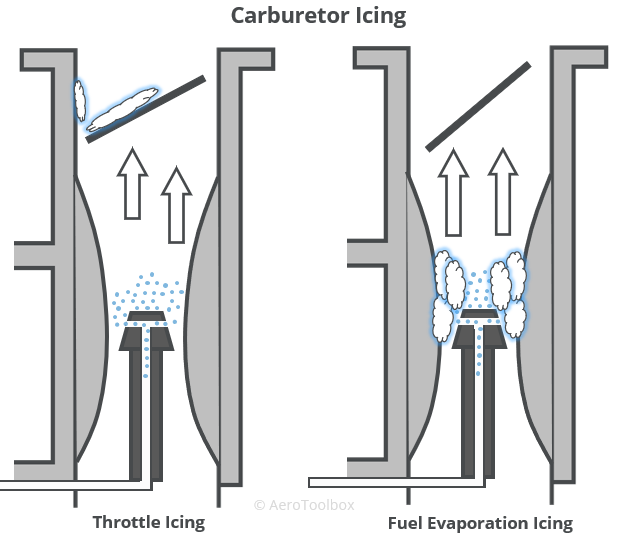
Fuel Evaporation Icing
The diffuser nozzle is located at the throat by design. This is where the atomized liquid fuel is introduced into the airflow and instantly vaporized. Energy is required to change the state of the fuel from a liquid to a gas. This is no different to how a kettle requires energy in the form of a heating element to boil the water and is termed the latent heat of evaporation. The energy required to evaporate the fuel is extracted from the air passing through the throat which has the effect of decreasing the temperature in the throat even further.
The combination of the temperature drop as a result of the geometry of the venturi and the drop due to the latent heat required to vaporize the fuel can quite easily result in a situation where the temperature in the throat drops below freezing. If this happens then any moisture in the air entering the venturi may freeze and stick to the side of the venturi.
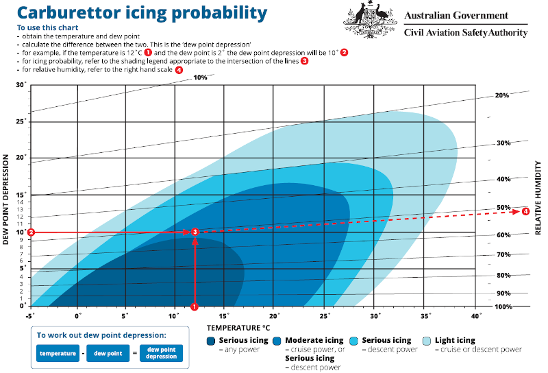
This type of icing is termed fuel evaporation icing and can take place in ambient temperatures as high as 100 °F (38°C) under the correct conditions of humidity. Icing is most likely to occur when temperatures are at or below 70°F (21°C) and relative humidity is above 80 %.
The icing probability chart below shows that carburetor icing can occur over a very wide range of temperatures and humidity’s and should always be in the forefront of a pilot’s mind, especially in critical phases of flight such as take-off and landing. Carburetor icing can be mitigated through the use of carburetor heating which will be discussed in more detail below.
Aerotoolbox has built a fully automatic Carburetor Icing Probability calculator making it easy to assess the risk of carb icing before embarking on your next flight.
Throttle Icing
Throttle icing is another form of icing that manifests itself due to the design of the carburetor. Here the ice forms on the rear side of the throttle valve, usually when the throttle is in a partially closed position. A region of low-pressure forms behind the throttle valve due to the resulting airflow, resulting in a steep pressure drop across the valve. The pressure drop lowers the temperature to below the freezing point and any moisture in the air freezes and is deposited on the valve.
Throttle ice restricts the passage of air to the engine in much the same way as evaporation icing, except that only a small volume of ice is required for an appreciable loss in power to occur. This is due to the already relatively restricted passage that the low throttle setting dictates.
Impact Icing
This is a third type of icing that can occur at or around the carburetor. Impact ice can collect on metallic components on cold days when the surface temperature drops below freezing. Usually impact ice manifests when flying through snow, sleet or freezing rain; the same conditions where the risk of icing on the airframe structure is high.
Identification and Prevention
Carburetor icing restricts the power output of the engine and so manifests as a loss in rpm in a fixed pitch propeller aircraft, and a loss in manifold pressure in an aircraft with a constant speed propeller. A rough running engine is another clear indication that icing may be a problem.
Carburetor Heat
Carburetor icing is prevented or removed through the use of carburetor heat. This is an anti-icing system that ducts hot air into the venturi to keep the carburetor above freezing. It can be used to melt ice that has already accumulated but is best used pre-emptively as a prevention measure.
Carburetor heat is applied through a lever in the cockpit. When activated the hot air that enters the venturi will be at a lower density than the ambient air. Initial application will therefore result in a drop in engine rpm (or a drop in manifold pressure), and an enriching of the mixture due to the introduction of less dense air. If used to remove ice that has already formed, application of the carburetor heat will initially cause the engine rpm to drop, before it begins to climb again as the ice melts and normal operation of the carburetor is restored. The mixture may need to be leaned during application to regain full power.
Atmospheric conditions should be monitored throughout a flight and full carburetor heat applied if icing is suspected. The heat should be left on even after any ice has melted and only turned off when the pilot is certain that the environment is no longer conducive to icing. Carburetor heat should only ever be used in the fully-on position and never at partial settings as this could cause the carburetor temperature to move into the icing temperature band. Some aircraft are fitted with a carburetor temperature gauge which can be useful in preventing and diagnosing carburetor icing.
Worried about carb icing? Why not try our new Carburetor Icing Probability calculator.
This brings us to the end of this tutorial on the carburetor. Thank you for reading and please remember to share this resource with your friends, colleagues, or fellow student pilots if you found it useful.


