Most internal combustion engines work on one of two principles of operation: a two-stroke cycle or a four-stroke cycle. Four-stroke engines are the predominant type seen in general aviation and form the topic of this post.
Piston Engine Cycles
Piston engines are classified according to the number of distinct steps that the engine performs in one complete engine cycle. Two-stroke engines complete a cycle in one revolution of the crankshaft with two movements; an up and down stroke of the piston which incorporates intake, compression, combustion and exhaust. Two stroke engines are common on microlights and some smaller ultralight aircraft, as these engines have a lower part count making them simpler to operate and cheaper to procure and maintain.
Four-stroke engines are the most common engine type in use in the general aviation industry and it is this engine type that we will study further. A four-stroke engine takes two crankshaft revolutions to complete one engine cycle with the piston moving through 180° to complete each step in the cycle. A four-stroke cycle includes an intake and compression step (one crankshaft revolution) and a power and exhaust step (one crankshaft revolution).
Cycle Nomenclature
There are a number of definitions that should be well understood before continuing with the details of the four-stroke cycle. Refer to the image below and the definitions underneath the image.
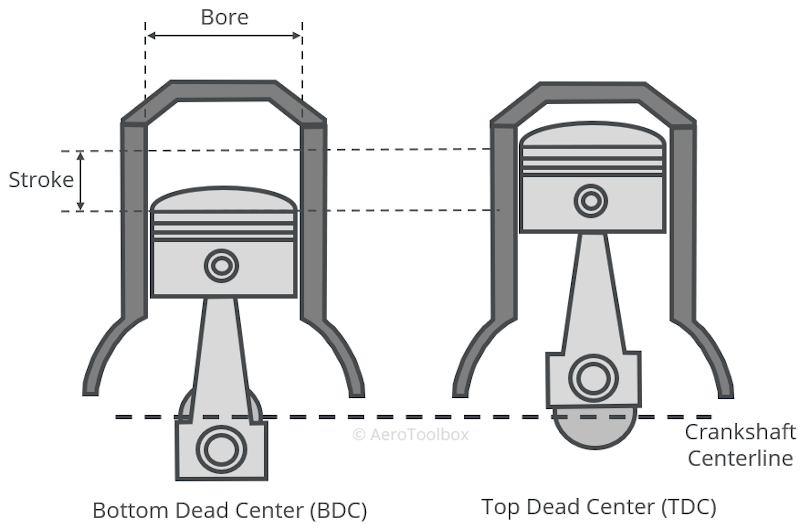
Top Dead Center (TDC) – this refers to the position of the piston when it is at the top of its travel. The piston is situated near the top of the cylinder head and the crankpin is at its uppermost position.
Bottom Dead Center (BDC) – this refers to the point in the cycle where the piston is at the bottom of its travel and the crankpin is at its lowest position.
Stroke – the stroke of the engine is the reciprocating distance that the piston moves in the cylinder from BDC to TDC.
Bore – this refers to the inside diameter of the cylinder.
Compression Ratio – the volume of the space in the cylinder can be determined with the piston at BDC and at TDC. The ratio between the two give the compression ratio. As an example, an engine with a compression ratio equal to 9 has a volume in the cylinder nine times greater with the piston at BDC than at TDC.
Swept Volume – this is the difference between the volume of the cylinder with the piston at TDC and at BDC. This can be calculated by multiplying the bore by the stroke:
$$ S.V. = \frac{\pi D^2}{4}\times Stroke $$
Where:
\( D: \) Cylinder Diameter
\( S.V.: \) Swept Volume
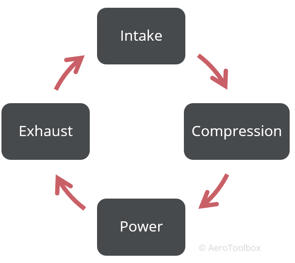
The Four Stroke Cycle
As long as the engine is running, it will continue to repeat the four steps in a four-stroke cycle continuously. Each step in the cycle represents a 180° movement of the piston which corresponds to a half-revolution of the crankshaft. Since it takes two crankshaft revolutions to complete one four-stroke cycle, the complete cycle will be completed at half the engine RPM e.g engine running at 3000 RPM will complete 1500 complete cycles in one minute.
The engine will always complete the cycle in the same order:
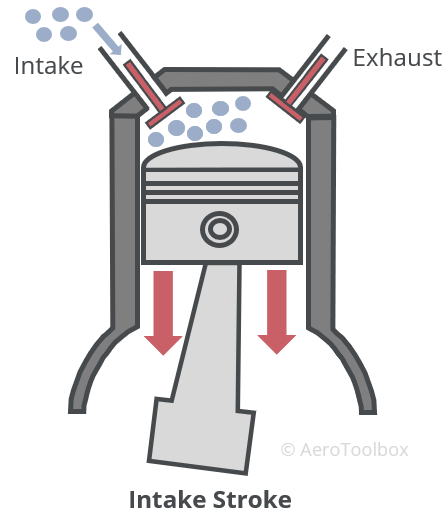
Intake or Induction
The purpose of the intake or induction stroke is to draw a mixture of air and fuel into the cylinder. This stroke takes place with the piston moving down from TDC to BDC. The inlet valve must be open to allow the air-fuel mixture into the cylinder while the exhaust valve remains closed. The downward motion of the piston causes the pressure in the cylinder to drop, which sucks the mixture into the cavity left behind by the piston’s motion.
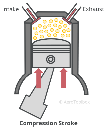
Compression
As the name suggests, the purpose of the compression stroke is to compress the air-fuel mixture that has been sucked into the cylinder head before ignition takes place. This is accomplished by the piston moving upward from BDC towards TDC. The motion of the piston reduces the volume occupied by the mixture, causing the pressure and temperature to increase inside the cylinder. The inlet and exhaust valves remain closed for the majority of the stroke (the inlet valve remains open approximately 50° past BDC to allow the optimal amount of mixture to enter the cylinder). As the piston approaches TDC, the spark plug fires, igniting the mixture. The spark is timed such that the inertia of the piston travelling upward is not retarded by the ignition but continues to TDC, where the stroke ends.
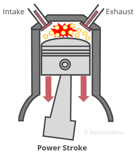
Power
The rapidly expanding gas ignited by the spark plug causes the pressure inside the cylinder to spike, forcing the piston back down from TDC to BDC. As the piston moves downward the increasing volume causes a reduction in pressure and temperature in the cylinder. It is this power stroke that forces the crankshaft to rotate, which ultimately drives the propeller and produces thrust. The inlet and exhaust valves remain closed for the majority of the power stroke with the exhaust valve opening just before the piston reaches BDC. The timing of the valve opening is set to ensure that the maximum power is produced while at the same time ensuring that the burnt gas is expelled in the most efficient manner during the exhaust stroke.
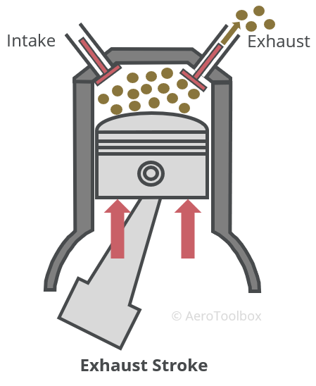
Exhaust
The exhaust valve opens just before the power stroke completes and remains open during the piston’s movement from BDC to TDC. The piston motion forces the exhaust gasses out through the open exhaust valve, clearing the cylinder before the intake stroke begins. This completes the cycle and the piston will start to move downward again as the induction step repeats.
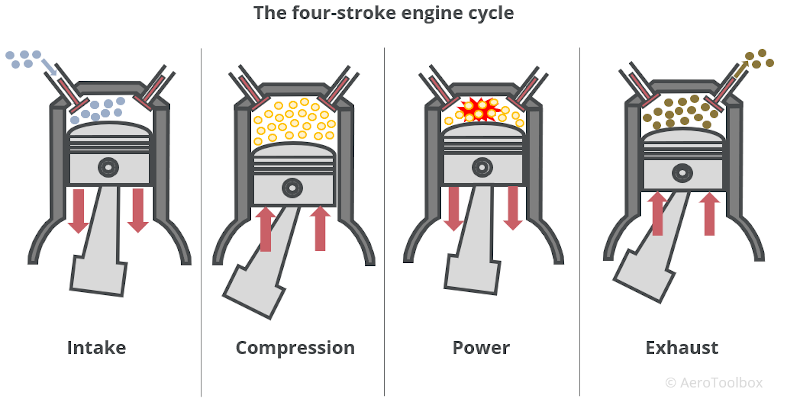
Complete Four-stroke Cycle
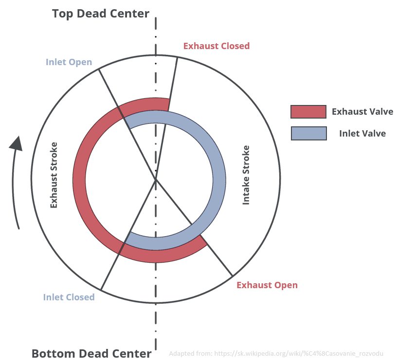
The complete cycle is shown in the image below.
Valve Operation
One fundamental property of all matter is that it possesses mass and therefore inertia. This means that just like a solid, the fuel-air mixture is subjected to Newton’s laws and requires a force to overcome its inertia and accelerate into the cylinder. This force comes from the pressure drop in the cylinder as the piston moves downward, but the movement of the gas is not instantaneous. Therefore, opening the inlet and exhaust valves at TDC and BDC respectively would not result in the maximum power being generated by the engine due to the inertia of the gas. As a result, the inlet and exhaust valves do not open and close at TDC or BDC but rather on either side of these positions to ensure optimal performance. It is important to remember that the pistons are moving at very high RPMs during normal engine operation which makes it very difficult for the gas to keep pace with the piston movement.
Valve lead – the valve is opened prematurely (before TDC or BDC) for optimal engine performance.
Valve lag – the closing of the valve is delayed (after TDC or BDC) to improve engine performance.
| Valve Lead | Valve Lag | |
|---|---|---|
| Inlet Valve | Inlet valve opens before TDC is reached during the exhaust stroke to prepare the cylinder to receive the fuel/air mixture as the intake stroke begins. | The inlet valve does not close as BDC is reached during the inlet stroke but is rather delayed until the piston is past BDC and has begun the compression stroke. |
| Exhaust Valve | The exhaust valve opens at the end of the power stroke just before BDC is reached. This allows the gas to be exhausted most efficiently during the exhaust stroke. | The exhaust valve is closed slightly after TDC just as the intake stroke begins. This assists in removing all the exhaust gas as the fresh mixture moving into the cylinder forces out the last remaining gas. |
The valve lead and lag results in a period around TDC and BDC where both the inlet and exhaust valves are open simultaneously. This period is defined as the valve overlap. The image below provides a graphical representation of the four-stroke engine cycle where periods of valve overlap can be seen by the overlap of the two colored arcs.
Otto Cycle
The four-stroke cycle described above results in pressure and volume changes to the gas inside the cylinder as the piston moves up and down through the various strokes of the cycle. The thermodynamic representation of this cycle is referred to as the Otto Cycle named after German engineer Nikolaus Otto; the first person to build a working four-stroke engine in the 1860’s.
The Otto cycle can be represented on a graph with Volume on the x-axis and Pressure on the y-axis, and describes the four-stroke cycle as follows:
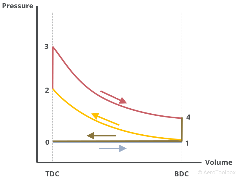
Process 0–1: gaseous fuel-air mixture (charge) of a fixed mass is pulled into the cylinder arrangement at constant pressure (Intake Stroke).
Process 1–2: the charge is compressed adiabatically (assumed no heat loss to surroundings) as the piston moves from BDC to TDC (Compression Stroke).
Process 2–3: the charge is ignited by the spark plug which causes the pressure in the cylinder to increase rapidly. This occurs at a constant volume and represents the moment that the piston is at TDC before moving down to complete the power stroke.
Process 3–4: The ignited charge causes the piston to move downward resulting in an adiabatic (isentropic) expansion of the gas (Power stroke).
Process 4–1: The energy (heat) released by the combustion of the charge has all been transformed into motion of the cylinder downward and the heat is dissipated in a constant volume process while the piston is at BDC.
Process 1–0: the mass of air and any residual fuel that remains after combustion is released to the atmosphere through the open exhaust valve in a constant pressure process (Exhaust stroke).
Cylinder Numbering and Firing Order
It is important to understand that the cylinders in any engine do not all complete the same part of cycle at the same time; rather they each fire in a particular sequence designed to keep the engine running smoothly and delivering continuous power to the propeller. Aircraft engine manufacturers will always label each cylinder on an engine and publish the engine firing order.
The firing order is designed to balance the engine as far as possible by ensuring (in the case of a horizontally opposed engine) that opposite pistons move in the same direction. A four-stroke, four-cylinder engine should have each cylinder completing one of the four strokes at any one time.
Pre-ignition and Detonation
Pre-ignition and detonation are two separate but similar phenomena that result in the fuel-air charge igniting prematurely causing damage to the pistons and a loss in power.
Pre-ignition: this refers to ignition of the fuel-air mixture before the spark plug fires and is caused by any source in the cylinder sufficiently hot to incite ignition. Common causes of pre-ignition are hot spots in the combustion chamber, a hot exhaust valve, an over-heated spark plug, or glowing pieces of carbon deposited in the cylinder. Pre-ignition generally occurs in one cylinder (the hottest cylinder), whereas detonation occurs in all cylinders simultaneously.
Detonation (knocking): during the compression stroke the fuel-air charge is subjected to a rapidly increasing pressure and temperature as the volume is reduced. The higher the compression ratio of the engine, the hotter the charge becomes. At very high compression ratios a situation may occur where the charge will instantaneously combust (explode) before the designated moment of combustion. This is known as detonation and causes a hammer-like blow to the piston instead of a controlled, smooth push during the power stroke. Detonation can occur when fuel of the incorrect octane rating is used. Higher octane fuels are able to withstand greater compression before igniting; it is therefore imperative that fuel of the correct octane rating for a particular engine is used. If the recommended octane rated fuel is not available, then the next highest octane fuel should be used. Using a lower than recommended octane fuel can leave one vulnerable to knocking.
Detonation can still occur even if the correct octane fuel is used. The following can also cause detonation if not remedied during flight:
- Flying with higher manifold pressures than recommended – this will result in the cylinder head temperature and pressure increasing beyond normal operating limits.
- Flying with too lean a mixture – leaner mixtures will increase the cylinder head temperature. Detonation can occur when adding power but failing to enrich the mixture before doing so.
- Allowing the cylinder head temperature to increase beyond normal operating limits due to lack of aerodynamic cooling. Air-cooled aircraft engines can overheat while climbing if not carefully monitored. It may be necessary to reduce the climb rate or perform a step-climb in instances where the cylinder head temperature is approaching its limits.
This brings us to the end of our discussion on the four-stroke internal combustion engine cycle. In the next post we move on to the more practical aspects of operating a piston aircraft. We will start in the cockpit and discuss the engine instruments common to most light aircraft, before moving to some common engine problems; how to diagnose them, and what to do if you see them during a flight.


