
The internal combustion (IC) engine is the powerplant used on almost all light general aviation aircraft today. Electrical aircraft motors promise a new and cleaner aviation future but are still a way off, powering prototypes but, have not yet entered mainstream adoption. We will therefore focus on the internal combustion engine in this series discussing light aircraft propulsion.
Reciprocation into Rotation
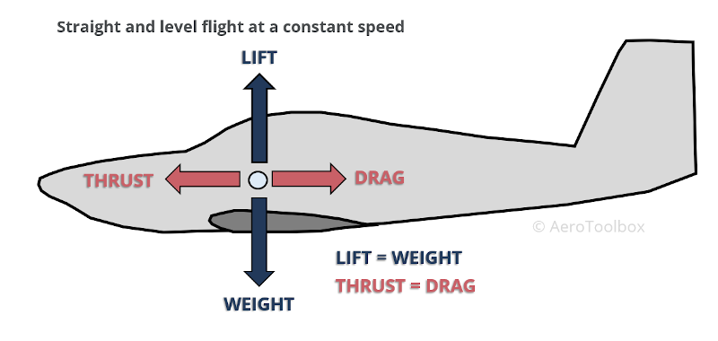
An aircraft in straight and level flight is subjected to four fundamental forces which must be balanced for the aircraft to remain in equilibrium. The weight of the aircraft is balanced by the lift produced by the wing and horizontal stabilizer in the vertical direction. As the airplane moves through the air, a resistance or drag force is produced which must be counteracted to maintain the forward flying speed. This counterbalance to drag is termed the thrust force and is generated by the engine-propeller combination.
An internal combustion engine works on the principle of converting reciprocating motion (pistons moving up and down) into a rotational motion (crankshaft turning) which is used to drive the propeller. Energy is required to move the pistons: this force is generated by the combustion of a mixture of fuel and air which forces the piston to move and so produces useful work. Chemical energy (fuel) is then said to have been converted into mechanical energy.
Let’s look at the various components that make up a typical internal combustion engine.
Components of an Internal Combustion Engine
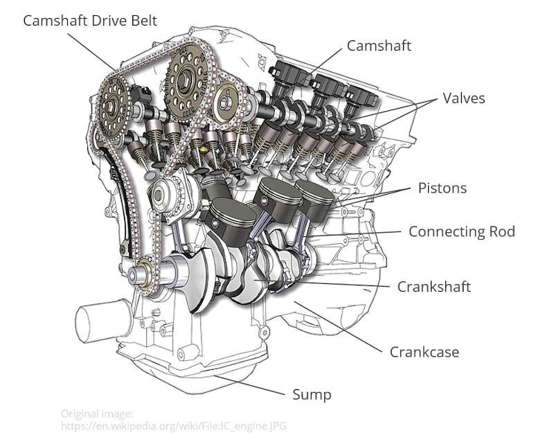
The image below shows the makeup of a typical internal combustion engine. Each of the major components is then discussed below.
Pistons
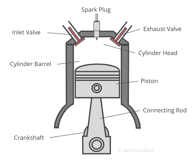
A piston is the reciprocating component of the engine and is responsible for transferring force from the expanding gases in the cylinder combustion chamber to the crankshaft via a connecting rod. Not shown in the cutaway above is the cylinder housing inside which each piston moves.
Pistons are usually cast from aluminium alloys. On higher performance applications (typically racing engines), the piston may be forged rather than cast. The piston does not directly contact the cylinder but a gas seal between the cylinder wall and the piston is maintained through the use of piston rings and oil lubrication. These rings are mounted in groves cut into the piston and are manufactured from cast iron. There are generally multiple piston rings installed, located just below the piston crown. Three different types of rings are commonly installed on an aircraft piston: compression rings, oil control rings, and oil scraper rings.
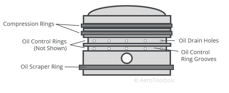
Compression rings are found at the top of the piston, just below the head. These rings ensure an airtight seal between the cylinder and the piston during the compression and combustion stroke of a four-stroke cycle.
Oil control rings are situated below the compression rings. The purpose of these rings is to allow oil to circulate from inside the piston to the cylinder walls. This circulation is accomplished through a set of small oil drain holes.
Oil scraper rings are situated near the bottom of the piston and are shaped such that they are able to scrape oil up and down the cylinder during the piston’s motion. Surplus oil is retained during the up-stroke and then returned to the crankcase during the downward stroke.
Crankcase
The crankcase is the name given to the housing that contains the crankshaft and the connecting rods which connect the piston to the crankshaft. The crankcase on an aircraft engine is usually made from a cast or forged aluminium. This provides sufficient strength and rigidity to hold the crankshaft in place while retaining the mass advantages of aluminium over steel.
Engine lubricating oil is stored at the bottom of the crankcase in a wet sump engine arrangement. The oil is cycled through the engine, lubricating the crankshaft, connecting rod bearings and other metallic components. The oil finds its way onto the cylinder walls, passing through the pistons, before draining back into the crankcase.
In a dry sump arrangement, the oil is not stored in the crankcase but rather in a separate external reservoir. The engine lubrication system is discussed in more detail in a post dedicated to engine lubrication and cooling.
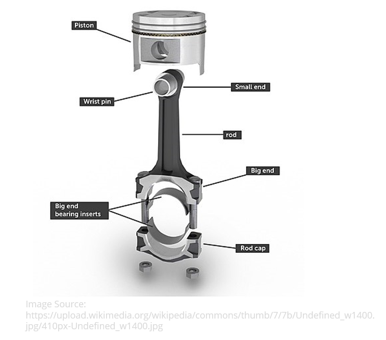
Connecting Rod
The connecting rod (con rod) is the metallic component that forms the link between a piston and the crankshaft. The connecting rods and the crankshaft convert the reciprocating motion of the piston into rotational motion at the crankshaft which is then used to drive a propeller and produce thrust.
Connecting rods are attached to the crankshaft via a cap and retaining bolts. A bearing installed inside the cap allows the connecting rod to translate the reciprocating motion of the piston into rotational motion at the crankshaft. The piston is attached to the connecting rod via a gudgeon pin (also called a piston pin or wrist pin) held in place through a set of spring clips.
Crankshaft
The crankshaft is the rotating shaft onto which the connecting rods and pistons are attached. As the pistons move up and down, this reciprocating motion is converted into rotary motion by the crankshaft. The crankshaft is housed in the crankcase and consists of journals, crank cheeks and crank pins.
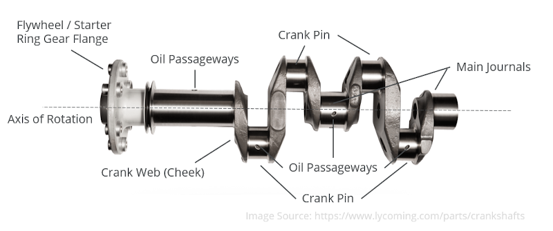
The connecting rods attach to the crankpins, and the crankshaft is supported by the engine block through a set of bearings at the crankshaft journals.
A flywheel is often attached to the crankshaft which stores rotational energy, and delivers a more consistent rotational speed than would otherwise be possible from the reciprocating pistons.
Valves
Any four-stroke internal combustion engine must have at a minimum two valves per cylinder: one to act as an inlet for a fuel/air mixture and one to exhaust the gasses after combustion. Aircraft engines generally make use of a two valve arrangement. Many automotive engines make use of a four-valve arrangement (two inlet, two exhaust) which improves the flow of intake and exhaust gasses.
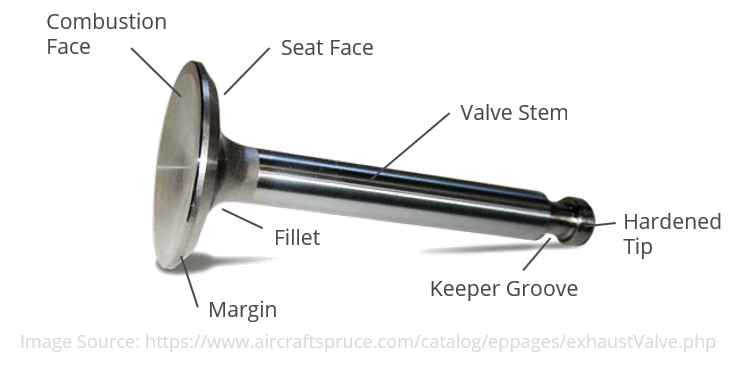
Valves must be able to retain their strength and shape at high temperatures and so are usually built from high strength steels. Exhaust valves are usually smaller than inlet valves so as to reduce the possibility of pre-ignition or knocking. The exhaust valve is usually the hottest part of the engine and a smaller valve reduces the likelihood that the high temperatures could cause the fuel/air mixture added during the intake stroke to ignite prematurely.
Both the inlet and exhaust valves are known as poppet valves and consist of a long stem, a neck, and a plug or head. The head consists of two faces: the combustion face and the seat face. The valves move up and down through a valve guide, opening and closing at defined times in the four-stroke engine cycle. The valve timing is determined by the rotation of the camshaft which is discussed next.
Camshaft
The inlet and exhaust valves are opened and closed by means of a camshaft which is driven off the engine by a drive belt connecting the crankshaft to the camshaft. In a four-stroke cycle each valve must open and close once in a full cycle which rotates the crankshaft through two full revolutions. The camshaft must therefore be driven at half the rotational speed of the engine – this is accomplished through mechanical gearing.
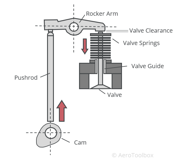
The camshaft is manufactured with a number of cams or lobes where each cam is situated above a valve and drives the motion of that valve. The shape of the cam determines how the valve opens and shuts and the orientation of the lobe determines the sequence in which the valve operates. It is easiest to visualize this motion by referring to the animation below.
On aircraft engines the valves are not operated directly through contact with the cam but rather through a pushrod and rocker system that connects the cam to the valve. This system allows for a clearance or gap to be present between the rocker arm and the tip of the valve. This clearance is essential as the temperature of the engine varies during operation which causes the valve to expand at higher temperatures. Without a clearance between the valve tip and the rocker, temperature increases would result in the valves opening late or closing prematurely which would cause the engine to run poorly and lose power. The clearance can be adjusted, usually through the adjustment of a screw on the rocker assembly.
Finally, two springs are incorporated into each valve to assist in closing the valve quickly and damping out any valve bounce that may occur due to the vibrations inherent in the running of an internal combustion engine.
Spark Plugs
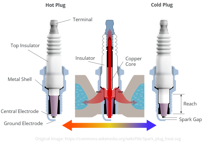
The purpose of a spark plug is to provide a means to ignite the fuel/air mixture that enters the inlet of the cylinder. This combustion then forces the piston down during the power stroke of a four-stroke cycle. A spark plug works by accepting a very high voltage from the aircraft’s ignition system which then jumps between a central electrode and the earthed exterior of the plug, resulting in a spark. This is similar to how a lightning bolt jumps between a cloud and the Earth. For this to happen the voltage must be very high – usually in the region of 5 000 V – 20 000 V. The spark occurs as the central electrode is insulated from the grounded exterior of the plug and so the high voltage must jump the air gap between the two resulting in a spark. Insulation is most commonly achieved using a ceramic insert which does not conduct electricity.
Spark plugs are classified as being either hot or cold plugs. The ceramic insert on a hot plug has a smaller area of contact with the metal part of the plug than a cold plug. Hot plugs therefore dissipate heat more slowly than a cold plug and are better suited to running in cooler lower compression engines. Conversely cold plugs are better suited to operating in hotter, higher compression engines as they are able to dissipate heat more effectively.
The spark plug must draw in the high voltage generated by the aircraft’s ignition system. The voltage enters the plug through a recess (terminal) which is held in place by a nut and covered in a weather-proof seal.
Aircraft engines always have two separate ignition systems in order to increase redundancy and reduce the risk of an engine failure during a critical phase of flight. Since the dual ignition systems are kept completely separate, each cylinder will have two spark plugs installed – one for each system.
Piston Engine Layouts
Internal combustion engines used on light aircraft generally adhere to one of a number of standard layouts, which are classified according to the arrangement of the cylinders relative to the crankshaft. We’ll introduce a few common layouts now.
Inline Engine
Inline engines are characterized by a vertical cylinder arrangement built in a single line along the crankcase. One advantage of this layout is the low frontal area that the engine presents to the oncoming air. A low frontal area means that the engine cowling can be made smaller which reduces the aircraft’s drag signature.
Difficulties cooling the rear cylinders in an inline arrangement usually limits the number of cylinders that can be accommodated on the engine.
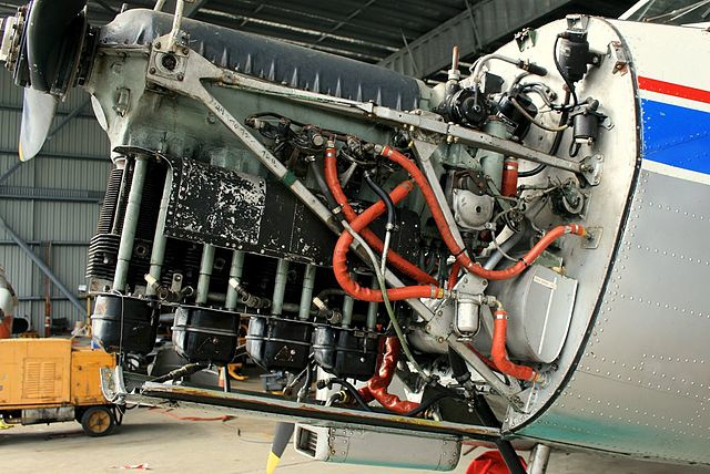
It can be difficult to install an inverted inline engine (like the deHavilland Gipsy Major shown below) onto an aircraft with a nosewheel due to the placement of the cylinders. These engines are therefore usually installed on aircraft with a tailwheel arrangement.
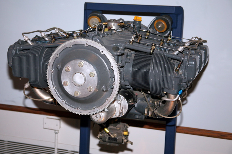
Horizontally Opposed (Flat) Engine
This is the cylinder arrangement most commonly seen in general aviation light aircraft. Here the cylinders are arranged horizontally in two banks with an equal number of cylinders on either bank. Every cylinder is coupled to a corresponding cylinder on the opposite bank to keep vibration to a minimum. The crankshaft lies centrally between the two banks of cylinders.
Horizontally opposed engines can be made shorter than an equivalent inline engine as the cylinders are placed in two banks rather than one. However, with this arrangement, the engine is wider and has to be manufactured with two separate cylinder heads rather than one.
The table below lists some of the most common horizontally opposed engines in service in light aircraft today and some examples of the aircraft they power.
| Engine Name | Aircraft Examples | No. Cylinders | Displacement | Power Output |
|---|---|---|---|---|
| Lycoming O-320 family | Cessna 172, Cessna 177, Piper PA-28 Cherokee, Piper PA-30 Twin Comanche, Robinson R22 | 4 | 320 cubic in (5.24 L) | 150 – 160 HP |
| Lycoming O-540 family | Cessna 182, Cessna 206, Piper PA-32 Cherokee Six, Vans RV-10 | 6 | 541.5 cubic in (8.87 L) | 230 – 350 HP |
| Continental IO-360 family | Cirrus SR20, Mooney M20, Piper PA-34 Seneca | 6 | 360 cubic in (5.9 L) | 180 – 225 HP |
| Rotax 912 family | Tecnam Echo, Diamond DA-20, CSA Sportcruiser | 4 | 74 cubic in (1.2 L) | 80 – 100 HP |
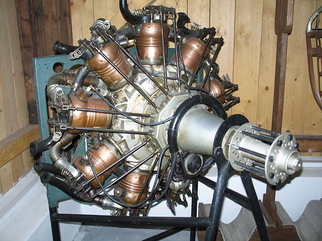
Radial Engine
Radial engines consist of a bank of cylinders arranged radially around a central crankshaft, similar to the spokes of a wheel. The cylinders in a given bank all lie in the same plane radially away from the crankshaft, such that not all the connecting rods can be attached directly to the crankshaft. Instead, one piston is connected directly to the crankshaft and all others connect to a ring on the master connecting rod via a master-and-articulating-rod assembly.
Four-stroke radial piston engines are always designed with an odd number of cylinders so that a consistent every-other firing order can be employed. This is done to leave a one-piston gap between pistons on the combustion stroke and compression stroke.
Radial engines were commonly used on larger aircraft where multiple banks of pistons could be installed to produce an engine with a large power output while maintaining as compact an engine as possible. World War II era aircraft such as the Republic P-47 Thunderbolt, Douglas C 47, and Avro Lancaster all made use of radial engines. Large Radial engines were largely rendered obsolete after the Second World War as jet engines and gas turbine engines could produce greater power, more reliably with a lighter overall mass.
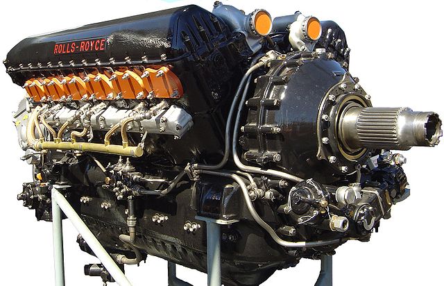
V-Type Engine
V-type engines are characterised by cylinders arranged in two banks in a V-arrangement when viewed along the axis of the crankshaft. By arranging the cylinders in a V-formation the overall dimensions of the engine can be reduced when compared to a horizontally opposed configuration. The angle between the two banks of cylinders is commonly referred to as the V-angle. Common angles are 90°, 60° and 45°.
One of the most famous V-configuration engines produced was the Rolls Royce V12 Merlin engine which powered a number of World War II aircraft including the Supermarine Spitfire, Hawker Hurricane, and de Havilland Mosquito.
This brings us to the end of our introduction to aircraft piston engines. In the next post we discuss the four-stroke operating cycle that underlies the operation of most aircraft internal combustion engines.


