In a previous post we introduced the various engine systems found on a light airplane. We now focus our attention to the ignition system, and specifically discuss the design and basic operating principles of a magneto.
Engine Ignition and Redundancy
A reliable and continuous source of ignition is required to keep an engine operating. Without ignition there is no means to burn the air-fuel mixture, which is sucked into each cylinder as part of the four-stroke engine cycle. In fact, ignition is so critical to the proper functioning of the engine that this system is designed to be completely separate from all other systems. This means is that even if there were a total failure of the electrical system, the engine would continue to operate as normal. There is an even further level of redundancy built into the ignition system; two magneto ignition systems are always installed on a single engine where each system is independently capable of keeping the engine running. Each system consists of a self-contained magneto, its own means to distribute the resulting high voltage to the spark plug, and its own set of spark plugs located in every engine cylinder.
The means by which a high voltage spark is created and distributed to each spark plug must therefore remain completely self-contained. Traditionally aircraft have used a magneto ignition system, which as the name suggests, utilizes rotating magnets and takes advantage of a physics phenomenon known as Faraday’s Law of Induction to generate the high currents and voltages required to generate a spark at the spark plugs. Let’s first describe in some detail the law of induction and then discuss how this is used in the magneto system found in your light aircraft. Finally, we will discuss the importance of always performing the magneto checks specified by the engine manufacturer as a part of your pre-flight checklist.
Magnetism and Electromagnetic Induction
To fully understand the functioning of a magneto we first must delve into the elementary physics behind magnetism and electromagnetic induction.
Magnetism
Everyone should be familiar with the concept of a magnet and most have at least one stuck to their fridge. A magnet can be described as any material that induces a magnetic field around it. Magnets all share a number of elementary properties:
- All magnets attract iron (this is why a magnet sticks to your steel fridge).
- Magnets always contain two poles (north and south). Cutting an existing magnet in two results in the formation of two separate magnets, each with their own north and south pole.
- If freely suspended one end of the magnet (pole) will always point towards magnetic north.
- Like poles repel each-other and opposite poles attract.
- There is a magnetic field set up around a magnet such that the lines of magnetic flux always leave the magnet at the north pole and enter again at the south pole.
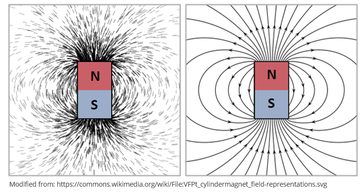
The strength of the magnetic field around a magnet can be described in terms of the magnetic flux. Magnetic flux is a measurement of the total magnetic field which passes through a given area.
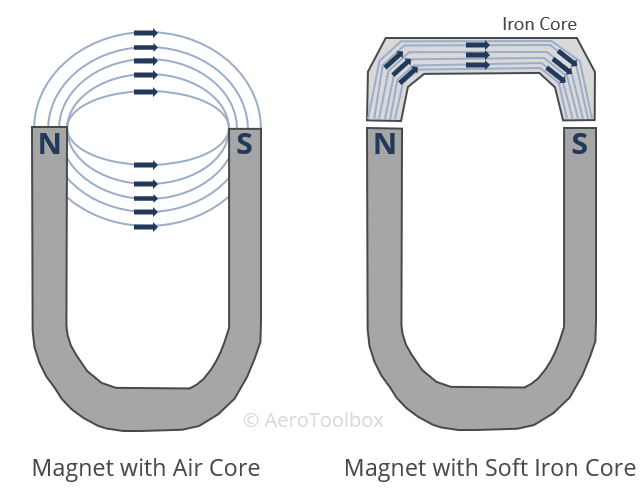
Flux lines will tend to seek the path of least resistance when moving from one magnetic pole to another. This magnetic flux will pass through air as can be seen when conducting the experiment of placing a magnet near a set of iron filings. However, a soft iron bar is a better conductor than air and so if such a core is placed between the poles of a magnet, the flux lines will concentrate together passing through the bar rather than the air. This principle of concentrating the lines of flux is one of the foundational principles that underpins the functioning of an airplane magneto.
Electromagnetic Induction
In the early 19th century Danish scientist Hans Christian Oersted discovered a link between magnetic fields and electric currents. He showed that a compass needle is deflected by a current carrying wire when cycling current through the wire. This is a very important observation: that current and magnetism are related. In fact, a changing magnetic field will always induce a current flow through a conductor and vice versa. This is the principle underlying the operation of electric motors and generators.
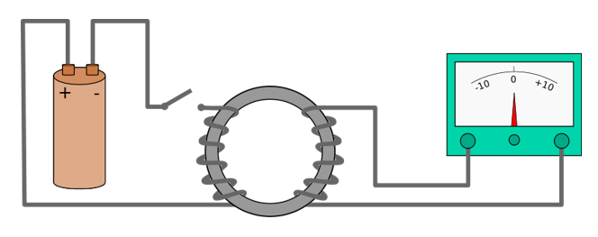
Further work by Michael Faraday in 1831 demonstrated the phenomenon of electromagnetic induction. Faraday’s experiment involved wrapping two wires around opposite sides of an iron ring (called a torus) and then closing a switch to allow current to flow through the wire wrapped around the left-hand side of the iron ring. He then observed that even though the right-hand circuit was completely disconnected from the left-hand circuit, when the battery was connected and disconnected, there was a flow of current induced on the right-hand circuit.
Faraday had induced a current flow through a change in the magnetic flux that occurred when the battery was connected and disconnected.
A magneto works on the principle of changing the magnetic field to induce a current in a wire. This current is then stepped up using a transformer to a very high voltage, which is sent to the spark plug, causing ignition of the air-fuel mixture in the cylinder.
Electrical Transformers
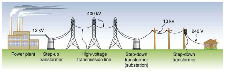
Electrical transformers find use in many fields. One of the most common applications of a transformer is in the stepping up of the voltage leaving a power station before being transported great distances along transmission lines, and then being stepped down before entering your home.
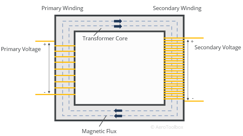
A transformer consists of two separate coils or windings wrapped around a soft iron core. The ratio of the number of windings on the secondary coil to the number of windings on the primary coil is proportional to the ratio of the voltages. This means that if you know the input voltage on the primary coil, and the number of turns on each winding, then you can easily calculate the output voltage on the secondary coil.
The primary and secondary windings are not attached to each-other but the voltage is induced on the secondary winding through electromagnetic induction. It is important to understand that electrical transformers only work when the current is constantly changing; that is, alternating current (AC) results in a changing magnetic field that accompanies the changing current. This allows the current and voltage to be induced on the secondary coil. A DC battery connected to a transformer like the one shown below will not induce any current or voltage on the secondary coil.
$$ V_{s} = V_{p} \frac{N_{s}}{N_{p}} $$
Where:
\( V_{s}: \) Voltage on the Secondary Coil
\( V_{p}: \) Voltage on the Primary Coil
\( N_{s}: \) Number of turns on the Secondary Coil
\( N_{p}: \) Number of turns on the Primary Coil
If the number of coils on the secondary coil is greater than on the primary coil, then the voltage in the secondary coil will be greater than at the primary coil. This is called a step-up transformer.
Conversely if the primary coil has a greater number of windings than the secondary coil, the voltage will drop across the secondary coil and the transformer is said to step-down the voltage.
Operating Principles of a Magneto
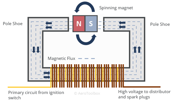
A common magneto design seen in light aircraft ignitions systems consists of a four-pole permanent magnet which rotates at high speed around a soft iron coil core and pole shoe arrangement. This induces a magnetic flux flow through the primary coil. The primary coil contains several turns of conducting wire which induces a current in the wire at the primary coil. A step-up transformer then increases the voltage at the primary coil to a value large enough to induce a spark at the spark plugs.
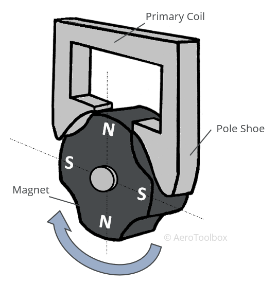
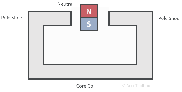
It is easiest to demonstrate the principle of magneto operation by simplifying the magneto to a single magnet rotating around a soft iron coil core.
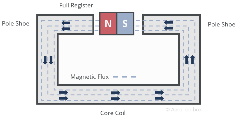
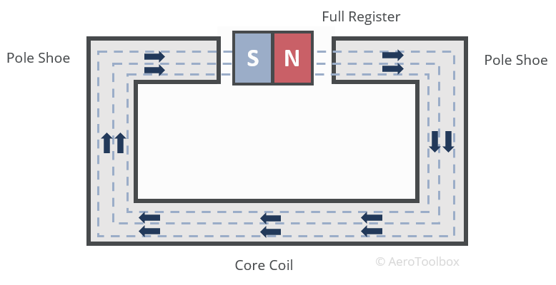
When the magnet is aligned with the pole shoes the magneto is said to be in the full register position and maximum magnetic flux passes through the core from the north pole to the south pole.
As the magnet rotates through 90° no magnetic flux able to pass through the coil core. The magneto is said to be in the neutral position.
The magnet continues to rotate through an additional 90° and the flux is once again able to pass through the coil core. This time however, the direction of the flux travel is reversed as the north and south poles have moved through 180°. The magneto is once again at the full register position but now the flux direction has reversed.
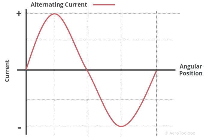
If we think back to the experiment that Faraday conducted where he was able to induce a current in a coil due to a changing magnetic flux, we will realize that this is exactly what we are doing by rotating our magnet past a core coil. The flux is continuously changing direction as the magnet rotates and so if we were to coil a current carrying conductor around the soft core, we can induce a current in the coil. The current that we induce will be an alternating current as the direction of the current flow changes with the change in magnetic flux direction.

This change in direction of the current in the coil is as a result of Lenz’s Law which states that the current that is induced through a conductor in a changing magnetic field must be such to oppose the direction of the changing flux. If the current did not oppose the changing magnetic field then a situation would arise where the induced current would cause the magnetic flux to increase which would induce a larger current which would in turn cause the magnetic current to increase and so on. This would violate the principle of the conservation of energy and would be equivalent to the creation of a perpetual motion machine. In reality, the induced current acts against the changing magnetic flux.
We now have a means to generate an alternating current induced by the changing magnetic field of a rotating magnet. The example given above was for a di-pole magnet (single magnet with one north pole and one south pole). Magnetos used in light aircraft are generally four-pole magnets which means that there are four positions of full register within one complete revolution of the magnet.
The voltage output at the primary coil is a function of the rate of change of the magnetic flux, which is a direct function of the speed at which the magnet in the magneto can be rotated.
Using our knowledge of step-up transformers, and knowing that we require a voltage somewhere in the region of 10 000 V to 12 000 V to send to our spark plugs, we can calculate the number of turns on the secondary coil required to step the voltage from 20 V to 12 000 V.
$$ N_{s} = \frac{V_{s}}{V_{p}}N_{p} = \frac{12000}{20} N_{p} = 600 N_{p} $$
A typical primary coil has 180 turns which would require that the secondary coil be made up of over 100 000 turns. This is not practical for a compact magneto to be installed in a light aircraft. Therefore, a means to increase the voltage at the primary coil before the transformer steps up the voltage is necessary. In this way the number of turns in the secondary coil can be reduced while keeping the output voltage at the required value.
The voltage induced in the coil is a function of the rate of change of magnetic flux. This is described mathematically by Faraday’s Law: $$ V \propto \frac{d\phi}{dt} $$
Faraday’s Law states that the larger the rate of change of flux, the greater the voltage induced in the primary coil. The rate of change of flux can be controlled in two ways:
- Increase the rotational speed of the magnet.
- Decrease the time over which the flux changes.
Since the magneto is spun off the crankshaft of the engine, it is not practical to just keep on increasing the rotational speed of the magneto to a point where the until the required primary voltage is met.
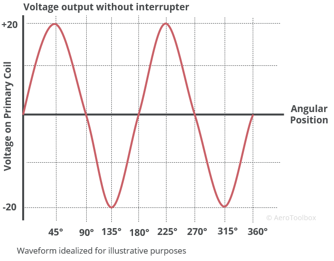
A further problem with just increasing the speed of the magneto is that the timing of the spark at the spark plug would become very difficult to manage as now the point at which the voltage peaks is a function of the magneto speed. Using this method, the spark timing of the engine would differ at every engine rpm.
The solution to this issue is to install a device called a current interrupter to the magneto. The purpose of the current interrupter is to change the output voltage on the primary and secondary coils from gradually increasing to a peak and then falling away to rather peak and then fall back to zero almost instantaneously. This is achieved by reducing the time component over which the flux changes direction. For those of you more mathematically inclined the purpose of the current interrupter is to reduce the \( dt \) or time through which the flux changes according to the formula for Faraday’s Law. By reducing this time, the voltage induced on the primary coil can be greatly increased to the point where many fewer turns on the secondary coil is required to generate the necessary high voltage to send to the spark plugs.
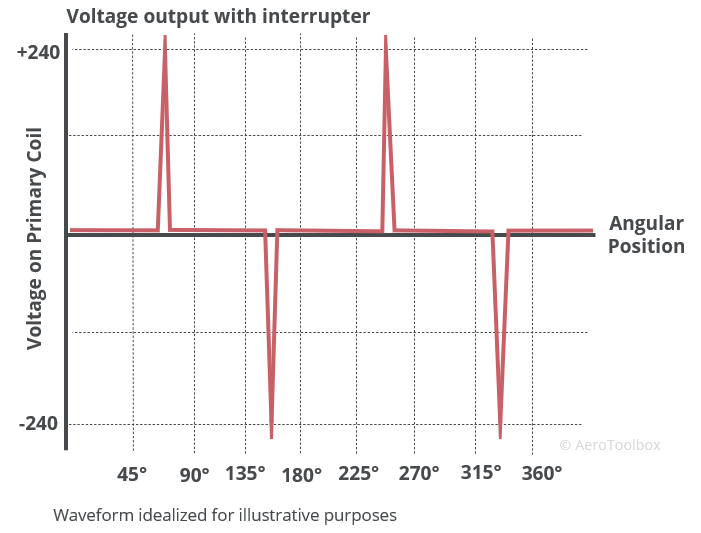
A standard light aircraft magneto with a current interrupter installed is able to generate 240 V on the primary coil with 180 windings which is then stepped up all the way to 24 000 V using a transformer with 18 000 windings on the secondary coil. The secondary coil contains 100 times more windings than the primary coil; stepping the voltage up by a factor of 100.
Typically, the spark plug will fire at a much lower voltage than the 24 000 V we have described above, perhaps closer to 5000 V during normal operation. When the sparking voltage is reached at the spark plug, the plug becomes conductive and current flows back to the secondary coil, which by Lenz’s Law opposes the flux change, reducing the current and voltage induced in the secondary coil. This regulates the magneto output and keeps it firing at the required voltage.
We now have a good picture of how send the high voltages required to the spark plugs, but not how the spark plug firing order is established. You know from the post on the four-stroke cycle that the spark plugs do not fire in unison but rather at the top of the compression stroke which occurs at staggered intervals in the engine, as each cylinder is at a different point in the cycle at any given time. The timing of the spark to each spark plug is controlled by the distributor.
The Distributor
Traditional light aircraft (Cessna, Piper etc) make use of a mechanically timed ignition. This means that the timing of when a spark plug will fire is not computer controlled but rather controlled using a mechanical device called a distributor. As the name suggests, the distributor’s purpose is to distribute the spark generated by the magneto and ensure that each spark plug fires in the correct order and at the correct time.
A distributor consists of a rotor, a distribution block, and a number of terminals equal to the number of spark plugs in the engine. The rotor is driven off the camshaft and rotates within the distribution block, passing each terminal sequentially.
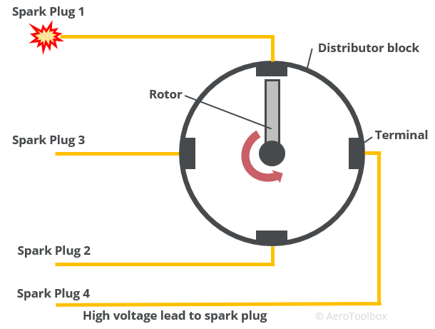
The distribution block is built from a material that will not conduct electricity. Each terminal is connected to a corresponding spark plug. High voltage from the magneto secondary coil enters the distributor and flows through the rotor arm. As the rotor arm rotates past each terminal the high voltage is passed from the rotor to the terminal, and on to the corresponding spark plug, causing that plug to fire. The rotor and the terminal do not touch but pass very close to one-another. The high voltage is then able to jump the gap and continue onto the spark plug via the high-tension leads.
For further details on the design and operation of spark plugs please refer to a previous post which covered this in more detail.
Magneto systems are either classified as High Tension (H.T.) or Low Tension (L.T.). This refer to where in the process the voltage is stepped up to that required to fire the spark plugs. In an H.T. system the voltage is stepped up to its final voltage within the magneto housing and then travels to the distributor and spark plugs through H.T. leads. In a L.T. system the transformer is located very close to the spark plugs and so the voltage remains lower for a longer period of travel. This has the advantage making the whole system lighter as smaller L.T. leads are used through more of the system.
Engine Starting Aids
The magnet found in each magneto system rotates through a mechanical connection to the engine. This presents a problem during engine start as the magneto is only effective at producing a spark that will cause the engine to fire once the magnet is rotating at speeds above 500 rpm. It is therefore necessary to make use of an alternate method to fire the engine before the magneto can take over and produce the sparks necessary for continued ignition. Let’s look at three different methods commonly employed to aid in starting a light aircraft engine.
The Induction Vibrator
This is a commonly used method to aid in starting the engine and involves bypassing the magnet portion of the magneto, and rather supplying the primary coil of one of the magnetos with a pulsating stream of DC taken from the battery. A mechanism called a vibrator is responsible for producing the pulses and operates using the principle of electromagnetic induction. The magnetic field that is set up as current flows to the vibrator causes a contact in the vibrator to open which stops the current flow and destroys the magnetic field. As soon as the magnetic field disappears the contact in the vibrator closes and current flows once again. This cycle repeats at very high frequency which sends pulses of voltage to the primary and secondary coil. These pulses can be transformed at the secondary coil as they are constantly changing; similar to an AC source.
These pulses of very high voltage travel to the distributor as a “shower of sparks” and on to the spark plugs to fire the engine.
Induction vibrators are found on aircraft that make use of an Off, Left, Right, Both and Start cockpit ignition switch like you would see in a Cessna 172. The induction vibrator is only connected to one of the two magnetos. The other magneto is grounded during start, and once the engine has fired and the ignition switch is moved back to the both position the engine will operate normally on both magnetos.
Impulse Coupling
An impulse coupling is another method that can be used to induce ignition before the magnetos have reached the rotation speed required to operate normally. An impulse coupling is usually attached to one magneto and consists of a spring-loaded coupling and a flywheel which delays, and then accelerates the magneto to a speed at which sparks can be generated. The impulse coupling also retards the spark, meaning that the spark will enter the cylinder at a later time than during normal operation. The engine therefore fires with the piston further along its travel which aids in starting the engine at lower rpms.
Booster Coil
The booster coil method of starting the engine involves bypassing the magneto all together and sending a high voltage generated through an induction coil directly to the distributor. When using a booster coil to start an engine, the distributor is modified to have two electrodes on the rotor. The main electrode is used during normal operation and is fed from the magnetos, while an auxiliary electrode is connected to the booster coil and is positioned such that it trails the primary electrode. This assists in delaying the spark sent to the cylinder which aids in starting the engine.
Ignition system in the cockpit
We’ll close this tutorial off with a discussion of the ignition system as operated by the pilot in the cockpit. We have already discussed that there are two independent magneto systems installed on a light aircraft in order to ensure sufficient redundancy is present in the system.
An aircraft engine will continue to operate on a single magneto, however it is never acceptable to get airborne knowing that only one of the two is functioning correctly. Performing a mag drop test is a part of every before-take-off checklist and involves running the engine up to a designed speed (usually around 1700 rpm in a Cessna 172), cycling through each of the magneto positions left, right, both, and ensuring that the magneto disconnects when grounded. The pilot will also observe the drop in rpm at each position and the delta between then. Aircraft manufacturers specify acceptable limits in rpm drop across the mags and if these limits are exceeded then the flight should not continue. If the drop is significant then one approach before abandoning the flight is to lean the mixture during the run-up. This increases the temperature in the cylinders in an attempt to burn off any deposits that may have accumulated on the spark plug. Repeat the mag drop test and if the drop is still outside the manufacturer’s limits then the flight should be aborted immediately, and the aircraft inspected by a mechanic before being released back into service.
This concludes our deep dive into the design and workings of the magneto ignition system. Next up we tackle the lubrication and cooling system of the engine. Thanks for reading and if you enjoyed this post and found it useful then please share it with you friends and fellow students.


