In a light aircraft, the power and torque generated by the engine while it is running is not only used to produce the thrust necessary to propel the aircraft forward. The engine is also used to power several systems necessary to keep the engine running and to safely operate the aircraft.
Engine systems are a large and important topic and so each major system has its own dedicated post describing how the system is designed, and its purpose. What follows here is just a short introduction to the various systems, with links to each of the larger posts.
The engine related systems have been broken down into two categories: those required to keep the engine running, and those that aren’t necessary to keep the engine operational, but are run off the engine and so only operate while the engine is running.
Systems required to run the engine
There are three major engine systems necessary to keep an internal combustion engine running. They are the ignition system, the lubrication system, and the fuel system.
Ignition system
The purpose of an engine ignition system is to provide a consistent supply of very high-voltage pulses to the spark plugs located in each cylinder. This must occur in the correct cylinder firing order, and at the correct moment in the engine cycle. Ignition is so critical to the functioning of the engine that this system is kept completely separate from all other systems (isolated from the electrical system). Additional redundancy built in by having two completely independent ignition systems installed such that the engine will continue to operate if one system fails.
Ignition of internal combustion general aviation engines is most commonly achieved through the use of duel magnetos. A magneto contains an engine-driven spinning magnet which induces an alternating current through a soft iron core by electromagnetic induction. This changing current is then stepped-up through a transformer to a very high voltage, before being sent to the spark plugs via a distributor.
Smaller and more modern aircraft engines, such as the Rotax 912/914 popular on many light sport aircraft, have done away with the magneto ignition system and instead use a fully electronic duel capacitor discharge system. This system is simpler than traditional magneto systems as there are no moving parts, which means that the ignition system requires practically no maintenance during the life of the engine. The same level of redundancy built into magneto systems are present on electronic ignition systems such that failure of one of the ignition systems will not cause the engine to stop running.
Refer to the article on the ignition system where aircraft magnetos are covered in far more detail.
Lubrication system
Internal combustion engines are comprised of many high-speed, high-temperature rotational components that move past one-another with small tolerances between them. As the temperature of the engine changes, these components expand (hotter) and contract (cooler). It is vital that the friction between these components be minimized at all times during operation and through all expected temperature ranges.
Engine oil is the primary lubricating agent and works by providing a thin film between engine components. The oil also aids in cooling the engine and forms a seal between the piston head and cylinder walls during operation.
The oil is continually cycled through the engine to extract and remove heat and to keep the oil at the required viscosity. Oil is pumped under pressure through the engine by a mechanical pump which is run off the engine, and passes through an oil cooler as part of the cycle. So long as the engine is running, the oil pump will continue to operate, keeping the engine lubricated. The pressure in the oil system is monitored by the pilot through an oil pressure gauge in the cockpit.
The oil system and cooling of aircraft engines is covered in more detail in a dedicated lubrication and cooling post.
Fuel system
A consistent supply of fuel to the engine is required at all phases of flight. Fuel is usually stored in the wings or in a tank behind the cabin and must reach the engine intake at a constant pressure while remaining clean of all impurities and contaminates. Fuel delivery is a critical requirement for flight and as such there is always redundancy built into the system design. Many aircraft make use of a mechanical pump driven off the engine to drive fuel under pressure from the tank to the engine, as well as a secondary manually selected auxiliary electrical fuel pump during critical phases of flight such as the take-off and landing. High wing aircraft with fuel tanks located in the wings have the added benefit that the force of gravity can be used to feed the fuel to the engine provided the engine is located below the wings, and the aircraft is not flying inverted or at negative g’s. These gravity-fed systems do not require a pump to bring the fuel to the engine but may still make use of an auxiliary pump during take-off and landing.
The type of fuel, the octane rating, and the ratio of air-to-fuel entering the engine are all important considerations that dictate whether the engine runs as the manufacturer intended. These are discussed in length in the fuel system post.
Auxiliary systems run off the engine
There are several important systems on the aircraft that are driven by the rotation of the engine via an accessory drive. Two auxiliary systems that run off the engine are introduced now: the electrical system and the pressurization system.
Electrical system
All modern aircraft require a continuous supply of electricity to run all the electrical systems found on an aircraft. This includes the avionics, aircraft lights, certain instruments, and in some cases the flap and undercarriage systems. It is impractical to satisfy this electrical load through a system of batteries alone, and so modern aircraft make use of an alternator to generate electricity through electromagnetic induction. An alternator converts mechanical energy (driven by the rotation of the engine) into electrical energy which feeds into the electrical system of the aircraft. This can be used to charge the battery and supply electrical energy to the various electrical components.
Pressurization system
Many light aircraft (particularly basic trainers like the C172 or Piper PA-28) are not routinely expected to fly at altitudes above 12 000 ft during normal operations and so are not manufactured with a cabin pressurization system. In these aircraft the cabin remains at ambient atmospheric pressure throughout a flight, which means that if the pilot wishes to fly at higher altitudes for extended periods then he/she should carry a supplementary supply of oxygen for himself/herself and every passenger on the flight.
The law regarding flight in an unpressurized aircraft at high altitudes is laid out in Federal Aviation Regulation Part 91.211 which states that no person may operate an aircraft at cabin pressure altitudes of between 12 500 ft and 14 000 ft for longer than 30 minutes without supplemental oxygen; and further, that a continuous supply of oxygen is required if flying at or above 14 000 ft. These rules differ slightly from country to country so be sure to check your local regulations before conducting a high-altitude flight.
This altitude restriction is overcome by sealing the cabin such that pressurized air can be pumped into the cabin, thereby reducing the pressure altitude experienced by the pilot and passengers. Provided this air results in the pressure altitude inside the cabin dropping below the limit for supplemental oxygen as laid out in Part 91.211, then oxygen marks do not need to be worn for the duration of the flight. Pressurized aircraft still require supplementary oxygen systems in case of an inflight depressurization emergency; these requirements are detailed in FAR Part 91.211(b).
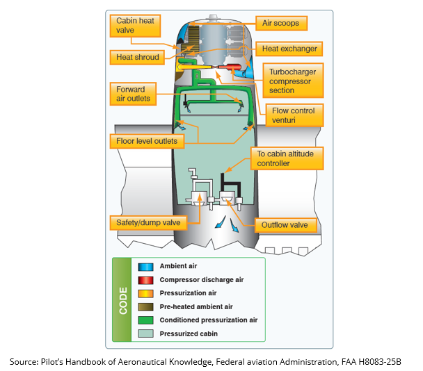
When pressurizing a cabin, ambient air must be first compressed in order to increase its pressure. This is done on piston engine aircraft by bleeding air off an engine turbocharger and ducting this air into the cabin. It important that the desired cabin pressure be maintained throughout the flight which means that air must be able to flow both into and out of the cabin. Pressure outflow valves are used to reduce the pressure in the cabin when necessary. It is also necessary to cycle the air in the cabin; especially during long flights where health concerns and unwanted odors start to become a factor.
It is typical to maintain a cabin pressure of approximately 8000 ft when operating a pressurized aircraft at its maximum designed cruise altitude. When pressurizing the cabin, additional stresses are introduced into the airframe structure as the structure now must oppose the pressure differential between the inside of the cabin and the outside ambient atmospheric pressure. The greater this pressure differential, the larger the stresses induced, and the heavier the structure would need to be to oppose this pressure. A cabin altitude of 8000 ft provides a reasonable balance between crew and passenger comfort and safety, while not overly penalizing the mass of the airframe structure.
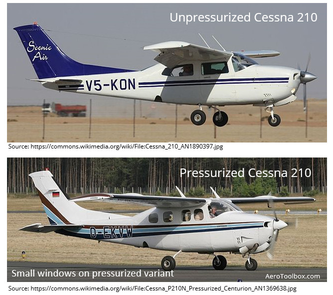
Pressurized light aircraft variants can easily be distinguished from their unpressurized siblings by the size and shape of their windows. Large windows with sharp corners introduce weak points to the airframe structure. These become stress raisers and crack initiators, where failure of the structure becomes more likely due to repeated cycles of pressurization and depressurization. For this reason, pressurized aircraft will always have smaller windows with rounded corners. A good illustration of these differences is shown below where the large windows of the unpressurized Cessna 210 variant is compared to the small, rounded windows of the pressurized P210 model. The main cockpit windshield of the P210 model also has a line of vertical bracing between the pilot and co-pilot seats for the same reason.
This concludes our introduction to the engine systems found on a typical light aircraft. Be sure to move onto the next post in this series which looks at the ignition system in much greater detail. Thanks for reading!


