An aircraft’s fuel system must be capable of providing a consistent delivery of fuel at the flow rate and pressure established by the manufacturer to ensure proper engine functioning under likely operating conditions. This includes any manoeuvre which forms part of the aircraft’s certification envelope.
The type and grade of fuel used must always meet the requirements specified by the engine manufacturer with respect to chemical composition and octane rating. In this post we’ll cover both the fuel and the fuel delivery system of a typical light aircraft.
Fuel Delivery System
The fuel delivery system includes fuel tanks and fuel lines, any fuel pumps necessary to move the fuel from the tanks to the engine, fuel strainers to prevent contaminated fuel entering the engine, a set of valves and vents to control the movement and pressure in the system, and a set of fuel level sensors and cockpit gauges.
There are two primary fuel delivery methods typically seen on light aircraft. The gravity fed system and the pumped system.
Gravity Fed
As the name implies, a gravity fed system relies on gravitational force to feed the engines from the tanks. This is only possible if the tanks are located higher than the engine, so gravity fed systems are typically seen on high wing aircraft like the Cessna 172. Regulations dictate that the system must provide a flow rate that is at least 150 % of the take-off fuel consumption of the engine throughout the certified flight envelope. In some cases, a booster pump is also installed to augment the gravity fed system – typically if the engine is fuel injected and not running a carburetor-based system.
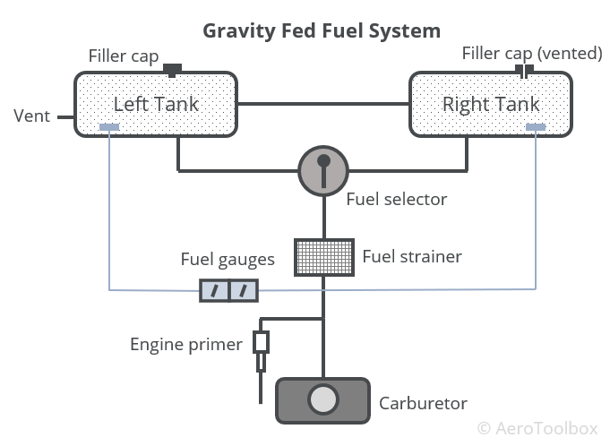
The two fuel tanks are mounted one in each wing and connected such that fuel can move between them (this is not the case with all high-wing fuel systems). There are two vents to the atmosphere within the system; this ensures that if one vent gets blocked, the system will remain at atmospheric pressure. The filler caps are placed on the top surface of each tank and must be designed to minimize the probability of in-flight loss or incorrect installation. Each tank has a sensor or float installed which is connected to a fuel gauge situated in the cockpit. It is important that the pilot always manually verifies the volume of fuel remaining in each tank by a visual inspection of the tanks before a flight. This provides a cross-check between the gauge reading and the actual quantity.
A fuel selector valve is placed in the cockpit so that the pilot can select from which tank to feed the engine. It is common on gravity fed systems to make use of a fuel selector that contains four positions: Left, Right, Both, Off. This gives the pilot the option of feeding the engine from both tanks or alternatively feeding exclusively from either wing tank. This option can be used to balance out the fuel distribution if one tank has a larger volume of usable fuel remaining.
Normal engine operation necessitates that the fuel entering the carburetor be free of all contaminants such as water or sediment. There is usually a filter at the outlet of each tank to catch larger debris, as well as a primary strainer positioned between the fuel selector and carburetor. This strainer prevents any contaminants from entering the engine or fuel pump. Cavitation in the pump as a result of air bubbles can cause permanent damage, and so the strainer is placed upstream of any pump mechanisms. A quick-drain valve is usually installed in the strainer which allows for any water to be drained out of the system during the pre-flight inspection. Water is more dense than fuel and so will settle to the bottom of the strainer.
An engine primer may be installed to assist in starting the engine if the aircraft uses a carburetor to atomize the fuel and mix it with the air entering the engine. The primer sprays fuel directly into the induction system, bypassing the carburetor. This has the effect of enriching the mixture, making it easier to perform a cold start.
Pump Fed System
Low wing aircraft with wing mounted tanks require a pump to move the fuel from the tanks to the carburetor or injectors. A system dependent on a pump to feed the engines requires a certain level of redundancy in the form of a primary main pump and a backup auxiliary pump. Both pumps must be independently capable of supplying the engine at a rate of 125 % of the maximum requirement throughout the certified flight envelope. If both pumps are operating simultaneously, then the fuel pressure may not exceed the inlet pressure limits of the engine. In a multi-engine aircraft, each engine must be capable of operating independent of one-another, and no fuel pump should be capable of drawing fuel from more than one tank at a time. A failure of any one component (excluding a fuel tank) may not result in a loss in power of more than one engine.
A typical pump-fed, low-wing, single engine fuel system is shown below.
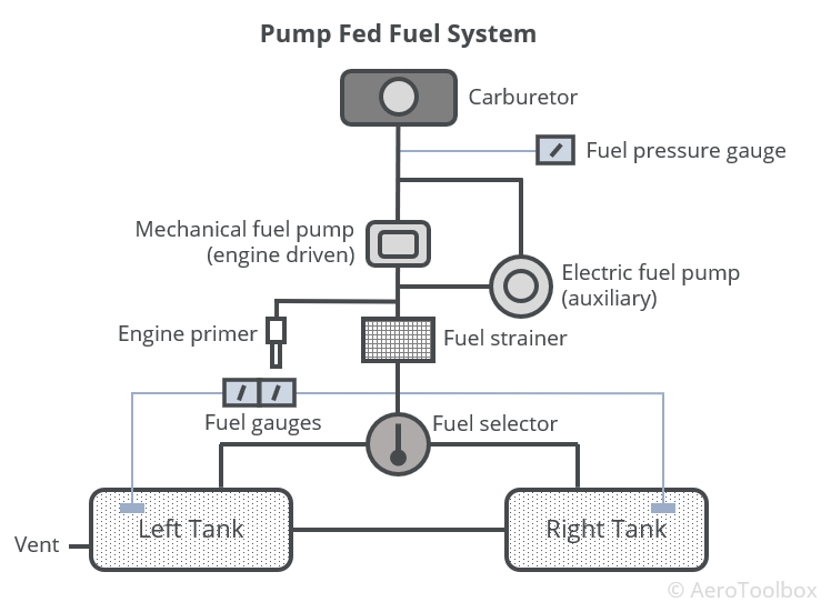
In addition to the components common to the gravity-fed system are the two fuel pumps (main and auxiliary) to feed the engine. During normal operation the main fuel pump, which is mechanically driven off the engine accessory drive, is sufficient to deliver fuel at the required pressure and flowrate. A backup electrical pump, which is driven off the aircraft’s electrical system, provides system redundancy in the event that the mechanical pump fails. This auxiliary pump is usually turned on during critical flight operations such as take-off and landing.
A fuel pressure gauge mounted on the instrument panel provides the pilot with a continuous indication of the fuel pressure at the engine inlet. This must be monitored by the pilot during flight, as a low indication could indicate that the mechanical pump is struggling to provide the engine with sufficient fuel. If this is the case, then the auxiliary pump should be turned on to maintain the required pressure in the system.
Fuel Tanks
Aircraft fuel tanks are subjected to vibration, aerodynamic forces, heat, cold, inertial loads, and even lightning strikes during typical operation. The tanks must be designed to withstand all these forces, and not deform under any loading in the design envelope. They cannot corrode from fuel storage, and measures should be put in place to minimize (ideally eliminate) the possibility that foreign contaminants such as dirt, dust, and water could find their way into the tank.
Tanks cannot be installed on the engine side of the firewall and there must exist at least half an inch clearance between the tank and the firewall if installed in the fuselage. They must be isolated from, and clear of personnel compartments by a fume and fire-proof enclosure. It is important that tanks remain ventilated at all times so that no accumulation of dangerous fumes or vapors occurs while in the air or on the ground.
Most aircraft make used of one or more of the three most common tanks in service today: integral tanks, rigid tanks, and bladder tanks.
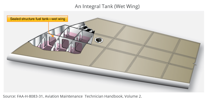
Integral Tank
An integral tank (often termed a wet wing) is formed by sealing the aircraft wing structure in the region designated as a fuel cell. An integral tank is generally constructed in an aluminium airframe as the aluminium alloy does not corrode when immersed in fuel. Adequate sealing of the storage region in the wing is very important, where every rivet, bolt, nut, fuel line and hose that penetrates the wing must remain completely sealed. The wing will flex under aerodynamic loading and expand and contract with ambient temperature changes. The sealing must be able to accommodate this through the range of operating temperatures and flight envelope.
Measures are put in place to limit the amount the fuel can shift and slosh during manoeuvres as the fuel is free to move about the wing structure. Baffles and guides are built into the wing to assist with this.
Integral tanks are usually lighter than the equivalent rigid metallic tank but may be more difficult to maintain and repair as the tank cannot be removed or replaced.
Rigid Tank
This is a self-contained tank which is built separately to the aircraft and installed in either the wing or in the fuselage structure. These are typically manufactured from three-series aluminium alloy or stainless steel and installed in special purpose fuel bays. These tanks are not integral to the structure and so must be adequately supported by the aircraft structure through the aircraft’s entire operating envelope.
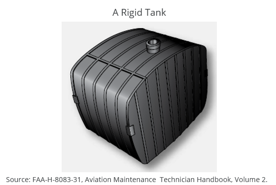
Removable tanks make repair and maintenance much easier than an integral design as the tank can be repaired outside the aircraft and reinstalled. Rigid tanks are subjected to pressure testing to ensure that they will not leak or collapse during flight at the edge of the flight envelope.
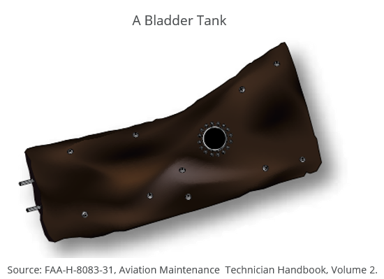
Bladder Tank
A bladder tank is similar to a rigid tank in the sense that the tank is manufactured separately to the airframe and installed during assembly. It is constructed from a reinforced flexible material like synthetic rubber and so, unlike a rigid tank, does not require a large a cut-out in the airframe structure to install. Installation may take place by rolling up the deflated tank, inserting the bladder through an inspection hole, and then un-rolling it into place. It is important to install a bladder tank without any wrinkles so that contaminants do not get trapped in the tank.
Tank Ventilation
Regardless of the type of tank used, each is vented to the atmosphere. This is done so that ambient atmospheric pressure is maintained in the tank at all times. This helps to prevent airlocks in the system which could occur if a vacuum was present in the tank. As the temperature in the tank changes, the density and hence volume of the fuel will change also. A tank vented to the atmosphere allows fuel to escape if expansion has occurred at elevated temperatures. Finally, by venting the tank to atmosphere any fuel vapors that have formed in the tank can be vented away. This prevents a vapor lock which could result in the engine no longer receiving fuel and ultimately stopping.
Drains
All tanks are built with drains installed at the lowest point in the tank. This allows for any sediments or water present in the tank to be easily drained away as the heavier contaminants will tend to settle at the bottom of the tank. It is for this reason that fuel is never drawn from the bottom of the tank but rather from a higher point where the fuel is more likely to be free of contaminants. This means that there is always a certain volume of fuel in a tank that is deemed unusable, which is why aircraft manufacturers quote a usable fuel capacity and a total fuel capacity.
Aviation Fuels
Every aircraft engine is designed around a certain fuel. It is never permitted to mix fuels, nor use a different fuel to that specified by the manufacturer. Reciprocating engines burn aviation gasoline known as Avgas, while gas turbine engines burn jet fuel.
Avgas differs from motor gasoline (Mogas) primarily in the additives that are used in its formulation. Avgas is a leaded fuel, containing tetraethyllead (TEL), which is a toxic substance used to raise the octane rating of the fuel. This prevents engine knocking (detonation) in high compression aircraft engines.
Avgas has a vastly smaller market then motor gasoline, as little as 0.14 % of the size of the mogas market in 2008 and continues to decline year on year. Many ultralight aircraft run on Mogas and the rise in popularity of these non-type certified aircraft means that the market for avgas will continue to decline. For this reason there is a gradual move by engine manufacturers toward replacing Avgas with the more readily available Mogas or diesel; in some cases this requires changes to be made to the engines, and in all cases the issue of a supplemental type certificate (STC) by the regulator.
Gas turbine engines do not run on Avgas but rather a kerosene-based jet fuel. The two most widely used jet fuels are Jet-A and Jet-A1. Jet-A is primarily used in the United States and Jet-A1 elsewhere in the world. The two jet fuel grades are very similar with differences primarily in the freezing point of the two fuels (Jet-A at -40°C and Jet-A1 at -47°C), and the addition of an anti-static additive to Jet-A1. Jet fuel is cheaper to produce than Avgas due to its simpler hydrocarbon chemical composition and lower volatility. A less volatile fuel is well suited for use in a jet engine as the fuel is injected straight into the hot combustion chamber.
Fuel Identification
It is vital that the correct fuel always be used when operating an aircraft. Since there are a multitude of fuels that may be available at any airport, a system is used where different colored dyes are infused into the different fuel grades for quick reference and easy identification.
The most common avgas variant available today is 100LL (Low Lead). The 100 designation refers to the octane rating of the fuel which is covered in the next section. This fuel is dyed blue. Older Avgas variants, Avgas 80 and Avgas 100 are much less common today and are dyed red and green respectively.
Jet fuel is colorless or straw colored and is distinguishable from gasoline as it does not contain dye.
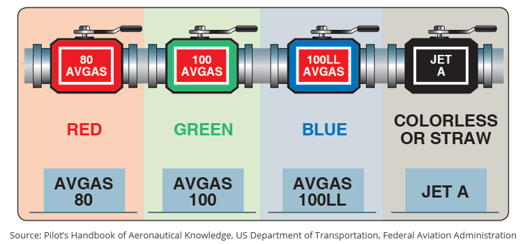
The labelling on all vehicles and services associated with the delivery and distribution of fuel is also standardized. Avgas is always labelled with white writing on a red background and jet fuel by white writing on a black background. This labelling extends to storage tanks, trucks and fuel hoses. Fuel caps on aircraft are also colored to this specification. The nozzles on jet fuel hoses are sized too large to fit onto an Avgas tank fill opening, and the fuel filler caps on the aircraft are also sized differently to prevent the incorrect fuel being uploaded.
Octane and Detonation
Gasoline fuels are always specified according to their octane rating as a means to compare the relative performance of the various fuels. The greater the octane rating, the more compression the fuel can withstand before igniting (detonating) under pressure. Higher compression engines therefore require a higher-octane fuel to avoid detonation.
Detonation is the condition by which the fuel in the combustion chamber of the cylinder is ignited prematurely by the rapid compression and associated temperature rise as the piston moves upward during the compression stroke. This ignition differs from the controlled burning of the fuel when ignited by the spark plug, and creates a powerful pressure wave through the cylinder, causing peak pressures far greater than that experienced during normal operation. This can be identified by a characteristic “pinging” or “knocking” sound in the engine, and so is sometimes referred to as “engine knocking”. Knocking can cause severe engine damage if allowed to continue.
Since higher octane fuels are formulated to withstand higher compression ratios, if follows that if the correct fuel is not available in an emergency, then fuel with the next higher-octane number should be used. Fuel of a lower octane than specified by the manufacturer should never be used as this could induce knocking and damage the engine.
Vapor Locks
The volatility of a fuel is a measure of how easily it vaporizes. The higher the volatility, the more likely the fuel is to form vapors at lower temperatures. This can be a problem on warmer days where fuel which has been heated by the sun may vaporize in the fuel line between the tank and the engine carburetor. This premature vaporization of the fuel can cause a blockage (or lock) which stops liquid fuel reaching the engine. A vapor lock in the fuel system can cause the engine to lose power or stop altogether. Mogas (motor car fuel) is more volatile than Avgas, making it more prone to vapor locks, especially in engines not designed to run on Mogas. Mogas should only be used in engines specifically certified to run on automotive fuel.
Engines running on Avgas can still suffer a vapor lock under certain conditions if care is not taken to avoid such a situation. Flights conducted at higher altitudes are more prone to vapor lock as the boiling point of fuel (vapors release when a fluid is boiled) decreases as the atmospheric pressure decreases. This may be mitigated through the use of a boost pressure pump which is turned on at high altitudes to keep the fuel in the tank under a pressure greater than the ambient atmospheric. The increased pressure acting on the fuel increases the boiling point of the fuel which keeps vapors from forming.
Refueling and Contamination
It is important to follow the correct procedure when refueling an aircraft to guard against the possibility of static electricity igniting the fuel as it is being discharged from the fuel bowser into the aircraft fuel tanks.
The action of friction passing over the surface of an aircraft or even through the flow of fuel through a hose during refuelling can cause that body to accumulate a charge. Certain items of clothing like woollen jerseys or nylon garments are also particularly prone to collecting a static charge. If there is a charge difference between two bodies, and these bodies are brought together, then the charge can jump from one body to the other in the form of a spark. This is the principle of static electricity and must be avoided when refuelling an aircraft, as this spark could cause the fuel to ignite.
To guard against the possibility of a fuel fire caused by a static discharge, one must always ground the aircraft and the refueler to the same source before beginning to upload fuel. A ground wire is connected from the refueler to the aircraft which equalizes the charge between the two. This must always be connected before the fuel nozzle is allowed to contact the aircraft.
The same principle applies when refuelling from a drum or can. The drum and the aircraft should both be grounded before refuelling takes place. Refer to your aircraft manual for further details and best refuelling practices for your particular aircraft make and model.
Preventing Fuel Contamination
We will end off with a few pointers on how to avoid fuel contamination. Contamination can occur as a result of sediment suspended in the fuel, or water which has condensed in the tank and entered the fuel. Fuel systems are fitted with filters and drains to remove moisture from the fuel before it enters the pump or carburetor, but these pointers can go a long way to minimize the risk of moisture entering the system.
- Always ensure that the fuel has been drained prior to a flight. Every aircraft is fitted with a fuel drain where water will tend to accumulate. This should always be checked and drained away prior to flight.
- The fuel from the drain should always be inspected in a transparent container where dirt or water will be more apparent. You should also drain sufficient fuel such that all fuel remaining in the lines leading to the tank is removed prior to your inspection. You must ensure that you are looking at fuel that has been sitting in the tank and not fuel that has remained in the line between the tank and the fuel strainer.
- If water or sediment is detected on the first sample, continue to drain the fuel until no contaminants are visible.
- Water is the primary contaminant to be aware of; fuel that is infused with water is cloudy in appearance if the water is in solution with the fuel, or otherwise visible as a separate layer below the fuel if the water has had sufficient time to settle at the base of the tank.
- If possible, fill the tanks immediately after a flight. If the aircraft has been flying at altitude for an extended period, the fuel will be cold. This cold fuel mixes with the warmer air that enters the tank once the aircraft is back on the ground. The combination of cold fuel and warm air provides an opportunity for condensation of the air to release water droplets into the fuel.
- Refuel the aircraft as early as possible before a flight commences. This provides the maximum time for any water in the fuel to settle to the bottom of the tank which is more easily identifiable than moisture is suspension.
This brings us to the end of this section on aviation fuel and the fuel system. Next, we look at the carburetor and how this device promotes the mixing of air and fuel in the correct ratio. If you enjoyed this post, then please share it with your fellow student pilots or those at your flight school.


