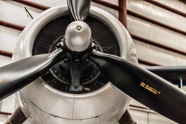
An internal combustion engine is designed to convert the reciprocating motion of the pistons into rotational motion at the crankshaft. This rotational motion is then be converted into a forward thrusting force by the propeller which powers the aircraft forward and is required to balance the drag produced by moving through the atmosphere.
This post will focus on the propeller and should provide a good overview of all aspects associated with light aircraft propellers. We will discuss the forces generated by, and acting on a propeller, the variables associated with propeller design, the types of propellers in use, and how the propeller should be operated and managed in flight.
Engine and Propeller Combination
A propeller does not operate in isolation but rather must be designed to work in unison with the aircraft’s engine. A poorly chosen propeller-engine combination will at best result in an aircraft that does not meet the performance requirements outlined by the aircraft designer. At worst, this could produce an inherently dangerous aircraft that may struggle to get airborne and could be prone to a complete engine or propeller inflight failure. If you are interested in a more technical discussion on how to size an engine and propeller then you are encouraged to read this post, where a propeller and engine combination is specified for a conceptual light sport aircraft.
Propeller Forces
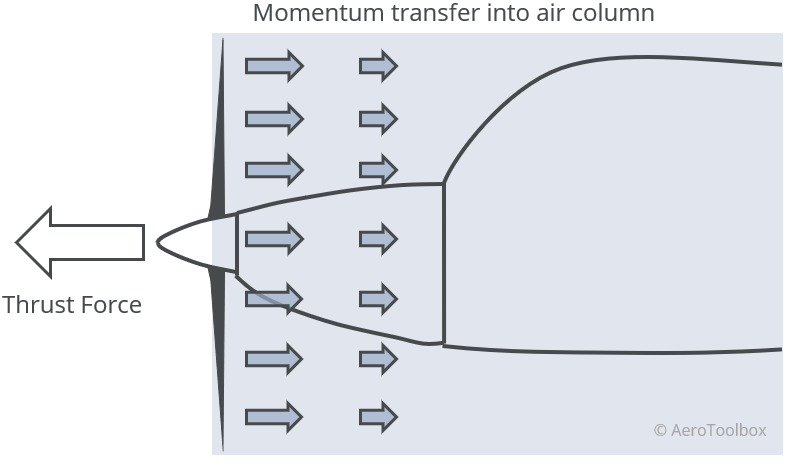
A propeller produces thrust through a momentum transfer from the propeller to the air by the rotation of the propeller blades. Momentum is the product of mass and velocity and you can think of the thrust generated as the reaction to the acceleration of a column of air with a diameter equal to that of the propeller.
Propeller Nomenclature
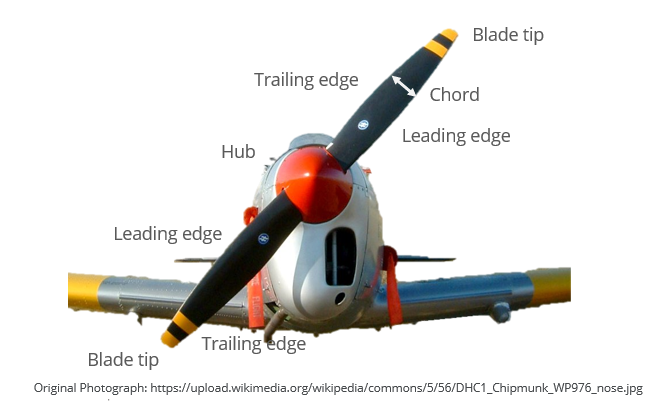
The terminology used to describe the various parts of a propeller blade are very similar to that of a wing. This should come as no surprise as a propeller blade is essentially a twisted, rotating wing. A blade has a root and a tip, where the tip is located the outer-most region of the blade. The root sections of each propeller blade come together at the propeller hub. Each blade has a leading edge (impacts the air first) and a trailing edge. The chord of each propeller blade joins the leading edge to the trailing edge and varies along the span from root to tip.
Resultant Angle of Attack
A propeller blade is nothing more than a wing with a twisted airfoil section which spins around an axis perpendicular to the direction of motion of the aircraft. Like a conventional wing a propeller blade will produce a lift and a drag force proportional to the square of the resultant velocity passing over the blade (relative airflow). Whereas a wing’s aerodynamic forces are a function of the forward speed of the aircraft, the propeller’s resultant velocity is a function of both the forward flying speed and the rotational speed of the blade (propeller rpm).
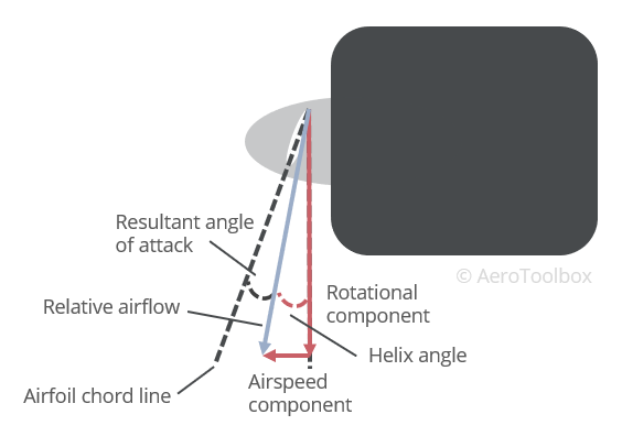
At higher airspeeds the airspeed component of the relative airflow increases, which reduces the angle of attack at a given blade angle. Conversely at lower airspeeds the angle of attack increases.
The helix angle is defined as the angle between the relative airflow and the plane of rotation of the propeller.
Twist is built into the propeller blade in order to ensure a more-or-less constant angle of attack along the span. The angle of attack along the span is a function of the rotational velocity component, which is a function of the radius from the hub to each spanwise location. If the blade was not twisted then the angle of attack would vary greatly along the blade, producing an unpredictable force distribution. The twist angle is a maximum at the hub, where the rotational velocity is the least, and a minimum at the tip which corresponds to the point of maximum rotational velocity.
Tip Speed and Helical Motion
The speed of the propeller varies with distance from the hub, increasing radially outward as this distance increases. The maximum speed of the propeller will occur at the tip and can approach the speed of sound if the propeller diameter is made too large.
The rotational velocity at the propeller tip is a function of the radius and the rotational speed of the propeller. The tachometer installed in the cockpit can be used to calculate the rotational speed of the propeller, remembering that some propellers are geared so the speed of the engine does not always equal the propeller speed. The tachometer is calibrated to revolutions per minute (rpm); to calculate the rotational speed at the tip requires that this is divided by 60 to read revolutions per second.
$$V_{rot} = 2\pi \times r \times rps $$
This is one component of the total velocity at the tip. The other component is simply the forward speed of the aircraft. These are the same two velocity components that form the relative airflow discussed above.
$$V_{trans} = airspeed$$
The speed at the tip of the propeller is the magnitude of the resultant between the rotational velocity and the forward velocity.
$$V_{tip-helical} = \sqrt{V_{rot}^2+V_{trans}^2}$$
If you trace the motion of a point on the propeller as an aircraft moves through the sky you will see that it makes a helical path, similar to the thread of a screw. This is because the resultant velocity is comprised of both a rotational and forward velocity component.
Thrust and Torque
A propeller bade is simply a rotating wing, which means that it will produce lift and drag in the same way as a conventional wing. However, it doesn’t make much sense to describe the resultant forces produced by the propeller in terms of lift and drag (normal and parallel to the helical flight path of the blade), but rather to resolve the forces into components normal to the direction of rotation of the propeller (thrust force) and parallel to the direction of rotation of the propeller (torque force).
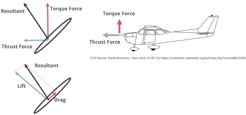
Once the forces are resolved in terms of thrust and torque it becomes clear that the lift force contributes both to the thrust and the torque components. The thrust force is dominated by the horizontal component of the lift force while the torque force is primarily a function of the vertical component of the lift generated by the blade.
In order to spin the propeller at a constant RPM the engine must produce sufficient torque at the propeller shaft to balance the torque force produced by the rotating propeller.
Forces Acting on a Propeller
Newton’s third law states that every action must produce an equal and opposite reaction. The propeller produces a thrust and torque force by imparting momentum to the air around it. The reaction to this is a set of forces imparted by the motion of the air on the propeller. The torque of the engine turning the propeller also imparts forces to each blade. A propeller must be strong enough to resist all the forces acting upon it throughout its design envelope.
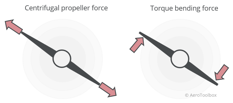
Centrifugal Force
A centrifugal force as a result of the rotation of the blades tends to want to pull the blades apart. This is the dominant force acting on the propeller and pulls the blade in tension.
Torque Bending
The air provides resistance to the rotational motion of the blade. This opposes the rotational motion, tending to bend the blade in the opposite direction.
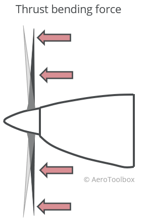
Thrust Bending
The blades tend to want to bend forward as a result of the thrust force generated.
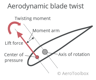
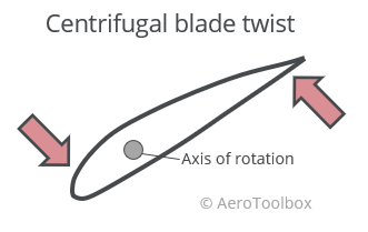
Aerodynamic Twisting
The resultant blade force acts at the center of pressure of each blade. If this point is not coincident with the line of action through the hub (axis of rotation) then a moment will be introduced which tends to twist the blade. If the center of pressure lies ahead of the axis of rotation, then this twisting force will tend to increase the angle of attack of the blade.
Centrifugal Twisting Force
Propeller Design Variables
There are three primary design variables that affect the operation of a propeller: the diameter, the number of blades, and the propeller pitch.
Diameter
A propeller produces thrust through a momentum transfer from the blades to a column of air approximately equal to the diameter of the propeller. It stands to reason then that increasing the diameter will increase the momentum (the mass component of the momentum equation), and hence the thrust. This is indeed the case and it is a well-established design practise to make the propeller as large as practically possible.
There are several limiting factors to the propeller diameter that can be accommodated on a given engine. The first is the increased torque requirement that a larger propeller brings. The moment of inertia of the blade increases exponentially with the blade diameter, which results in a much larger resulting propeller torque. The engine must be able to provide this torque if the propeller is to be used. A larger diameter also results in much larger centrifugal forces in the blade with higher resulting stresses that much be accommodated.
Another important consideration is the clearance between the tip of the propeller and the ground. The diameter should be specified such that the aircraft can be operated safely when taking-off and landing without the risk of a propeller strike in these critical phases of flight.
Finally, increasing the blade diameter also increases the tip speed. If the diameter gets too large then the tip could reach sonic speeds which results in noise, vibration, and a large increase in drag. This is undesirable and should always be avoided.
Number of Blades
The number of blades, the width (chord), and the diameter of the propeller determine the total blade area. Generally larger engines that produce more power require a greater number of blades to extract that power and convert it into useful thrust.
The propeller solidity ratio is the ratio of the part of the propeller disc which is solid to that which is air. It is measured at a particular radius from the hub, usually taken at 70% of the radius.
$$ Solidity = \frac{number \ of \ blades \times chord \ at \ radius \ r}{circumference \ at \ r} $$
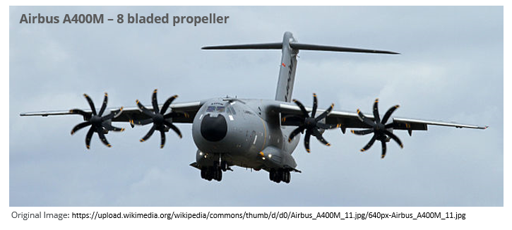
Increased solidity allows the propeller to absorb more of the engine power which is why a large powerful turboprop like the Airbus A400M requires eight-bladed propellers to efficiently extract maximum thrust from its engines.
Pitch
Pitch broadly refers to the ease with which a propeller can spin through the air. Since pitch is largely defined by the blade angle these two terms are often used interchangeably. Pitch is most easily explained using an analogy to the gearbox in a car. When pulling off from a stationary start, a low gear is selected, which allows the engine to spin up quickly and get the car moving. However, remaining in a low gear for the duration of the drive is very inefficient and will limit the car’s top speed as the engine hits the rev limiter quickly, and is unable to supply the power needed to drive at a faster speed. Similarly, trying to pull off in a car from a high gear will stall the engine, as the high gear ratio will limit the ability of the engine to produce the torque and power required to accelerate to the desired driving speed.
This is analogous to the pitch of a propeller. Instead of gear ratios, we talk about the pitch being either fine (low gear) or coarse (high gear).
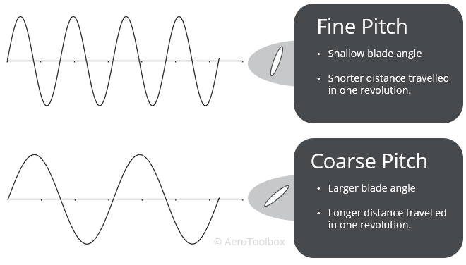
A fine-pitch propeller has a low blade angle, will rotate easily without taking a big bite out of the air, and will move forward through the air a short distance every revolution. This allows the engine to spin easily and operate at a high speed (rpm).
A coarse-pitch propeller has a high blade angle, will take a large bite out of the air with every turn, and will move forward through the air a large distance every revolution. A coarse pitch setting will limit the speed at which the engine can operate.
The angle that the blade makes with the relative wind will determine how much lift and drag (thrust and torque) is produced. The resultant angle of attack is a function of both the rotational velocity of the blade as well as the forward airspeed of the aircraft.
As the forward speed increases, the resulting angle of attack decreases at a given pitch angle. A propeller has a lift curve similar to a conventional wing with a linear lift region and a stall region beyond a critical angle of attack (usually around 15 degrees). It is therefore possible that the propeller can stall if the resultant angle of attack is too large. In the same way, if the angle of attack is too small the propeller will be operating at a low lift coefficient and won’t be able to efficiently produce the thrust and torque required.
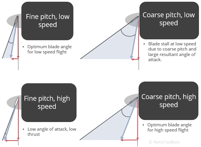
Clearly it is important to match the blade angle (propeller pitch) with the desired flight condition. A fine pitch at high speed is very inefficient as the resulting angle of attack is too low to produce the forces required. Similarly, a coarse pitch at low speed results in blade stall as the angle of attack is too large. Based on these examples above we can make some conclusions regarding the efficient operation of a propeller during the various phases of flight.
- Take-off and landing occur at low speeds and therefore a fine pitch configuration is most preferable to produce the greatest thrust (or to have the greatest possible available thrust in the case of a go-around during landing).
- Cruise is generally flown at relatively high speeds and as such a coarse pitch is the most efficient configuration to generate the thrust required to overcome the cruise drag.
This forms the basis for a variable pitch propeller where the pitch angle can be adjusted to best suit the various phases of flight.
Types of Propellers
Propellers are broadly classified by whether or not their blade pitch is adjustable and vary from relatively simple fixed pitch propellers to mechanically complex self-governing constant speed types.
Fixed Pitch
This is the simplest propeller type where the pitch is fixed at installation on the aircraft. This results in a propeller where the resulting blade angle forms a compromise between take-off (finer pitch) and cruise performance (coarser pitch).
Fixed pitch propellers are usually classified as either a climb-pitch or cruise-pitch propeller.
A climb-pitch propeller will have a finer pitch resulting in good take-off and climb performance, with relatively poorer cruise performance.
A cruise-pitch propeller will have a coarser pitch which advantages cruise performance over take-off performance.
Since the propeller is directly linked to the engine, the rotation speed of the propeller is a direct function of the engine speed. For this reason, the propeller speed will vary with airspeed, altitude, aircraft attitude and engine throttle setting.
A fixed pitch propeller may represent a compromise, but the reduced complexity that it offers results in a much simpler (and cheaper) propeller. For this reason, fixed pitch propellers are widely used on entry-level aircraft like the Cessna 172 and the Piper PA-28.
Some fixed pitch propellers are ground adjustable which means that the blade angle can be set before flight while the airplane is still on the ground. This allows for the propeller to be setup for a particular flight profile: either in a climb-pitch or cruise-pitch setting.
Variable Pitch and Constant Speed
A variable pitch propeller is one where the pilot is able to adjust and control the blade angle during flight. This allows for a large range in power settings and propeller speeds to be set, meaning that the most efficient operating point can be selected based on a desired airspeed and flight level. The pilot selects a fully fine pitch during take-off and landing, adjusting the propeller to be more coarse during the cruise in order to run the engine more efficiently at a lower rpm.
Variable pitch propellers can either be manually adjusted or mechanically governed to maintain a constant speed irrespective of the flight condition.
A manually operated variable pitch propeller does not make use of a speed governor and so the propeller speed can still vary in a manner similar to a fixed pitch propeller if airspeed, engine rpm, and attitude are varied while operated at a given pitch.
A constant speed propeller is a subset of the variable pitch type. These propellers are fitted with a mechanical governor which automatically adjusts the pitch of the blades to keep the propeller speed constant during flight. This allows the pilot to vary the power setting at a given propeller speed with the use of the throttle only as the governor makes the necessary adjustments to keep the propeller rpm constant.
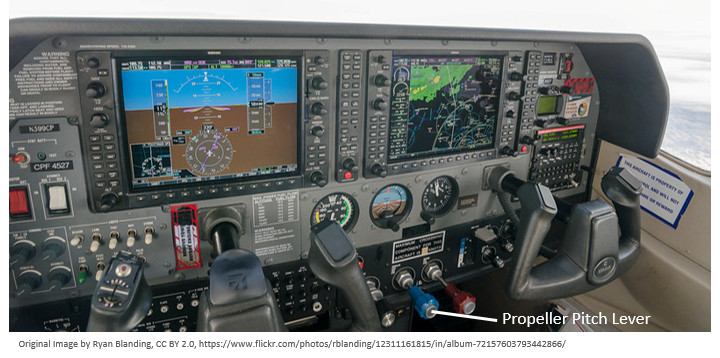
The propeller pitch is controlled through a lever in the cockpit similar to the one shown below. When flying with a variable pitch or constant speed propeller it is up to the pilot to monitor both the rpm and the inlet manifold pressure of the engine to ensure both remain within operating limits.
Managing the Propeller in Flight
Changing Power Settings
When flying a fixed pitch propeller aircraft, the engine and propeller rpm is directly tied to the power (throttle) setting. Opening the throttle will increase the rpm and vice-versa. If a fixed pitch aircraft is climbed, the rpm of the propeller and engine will automatically decrease, and diving in a fixed pitch aircraft will cause the rpm to increase. It is important to monitor the rpm in order to avoid an overspeed of the propeller.
This is not the case when flying an aircraft with a constant speed propeller. If the power is increased by opening the throttle, the governor on the propeller will automatically coarsen the propeller pitch to maintain the same rpm. This is undesirable if the intention of the pilot is to climb. In a climb the airspeed will drop, and a finer pitch will be required to extract the maximum power out of the propeller.
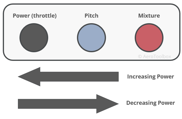
It is important that the three engine levers (power, pitch, mixture) are used in the correct order when the pilot wishes to add or reduce power. Operating the engine and propeller incorrectly could damage both the engine and propeller.
Increasing Power to Climb
When increasing power, the pilot should always operate the engine levers from right to left assuming a conventional engine lever set up. That is:
- First enrich the mixture to cater for the additional power requirement of the engine.
- Next set the pitch to the climb RPM – this propeller speed will be maintained during the climb by the governor.
- Finally increase the power to the desired manifold pressure.
Making adjustments to the propeller and engine in this order will ensure that the correct engine speed is maintained during the climb, and that the engine has sufficient fuel entering the mixture to accommodate the additional power requirements.
Reducing Power
The opposite is true if the pilot wishes to reduce power. This is a common occurrence once the climb has ended and the pilot wishes to throttle back to a cruise power setting.
When decreasing power, the correct order to adjust the engine levers is from left to right. That is:
- First set the desired manifold pressure by adjusting the throttle.
- Secondly reduce the pitch to the desired cruise rpm.
- Finally lean the mixture for cruise.
Effect of Propeller on Aircraft Control
Torque Effects
If you have ever tried to take-off in a single engine aircraft, you have no doubt noticed the tendency for the nose to swing to the left as full power is applied (clockwise rotating propeller as seen from the cockpit). This is due to the clockwise torque generated by the propeller, which according to Newton’s third law will cause the aircraft to react with an anti-clockwise torque of equal magnitude.
This anti-clockwise torque will push the left wheel down into the runway, increasing the friction on that wheel while relieving friction on the right wheel. With more friction on the left wheel the right will overtake the left, causing a turn to the left. This is compensated for by the application of right rudder to keep the nose straight.
Slipstream Effects
A clockwise rotating propeller (as seen from the cockpit) will cause a slipstream over the fuselage that will tend to cause the aircraft to yaw to the left. If left uncorrected (application of right rudder to correct), the aircraft will first yaw to the left and then begin a roll as the yaw angle increases (the secondary effect of yaw is roll). This tendency to yaw and then roll is most noticeable at high power settings when the aircraft is at a low speed but may be observed at any phase in flight.
Tail-wheel Aircraft
The nose-high attitude of a tail wheel aircraft produces two effects which will induce a yaw to the left during the take-off roll (clockwise rotation of propeller as viewed from the cockpit).
During the start of the take-off roll, the aircraft sits at a nose high attitude which induces a higher angle of attack on the down-going blade relative to the up-going blade. This causes a greater thrust force to be generated on the right side of the propeller which will induce a yaw to the left. This is known as the asymmetric blade thrust phenomenon and as only observed while the tailwheel is still on the ground. As the tailwheel comes up and the attitude of the aircraft reduces, this asymmetric thrust effect reduces.
The raising of the tail in a tailwheel aircraft during the take-off roll produces a gyroscopic precession to the left which must be corrected by the use of right rudder.
The asymmetric thrust and gyroscopic precession effects do not act together as the asymmetric effect is a function of the nose high attitude at the start of the take-off run, and the gyroscopic effect occurs as the tailwheel is lifted. In both cases the application of right rudder is necessary to keep the aircraft tracking the centerline.
This brings us to the end of this propeller tutorial. If you are interested in a more technical discussion on the sizing of an engine and propeller combination to meet a desired cruise speed, then I’d encourage you to take a look at this article. As always, if you enjoyed this post or found it useful as a study aid then please let your fellow student pilots know about AeroToolbox.com and share this on your favorite social media. Thanks again for reading.


