Introduction
Welcome to Part 10, the final installment in the Fundamentals of Aircraft Design series. In Part 9 we completed a preliminary drag estimation of a new light sport aircraft design. In this tutorial we build on from the drag estimation, and specify an engine and propeller combination in order to determine the variation in thrust with airspeed. By superimposing this thrust curve onto the drag graph, we can calculate the aircraft’s theoretical maximum speed, or the aircraft's speed at various engine power settings. Let’s get started.
This is the final installment of this Fundamentals of Aircraft Design Series. In Part 9 we completed a drag polar and plotted the total aircraft drag variation with the aircraft velocity, assuming that the aircraft was flying at sea level in a standard atmosphere.
We will be using the drag plot created in Part 9 for this tutorial, so it is recommended that you read through Part 9 before continuing.
A Quick Recap
The sketch below shows a plan view of the two-seat conceptual Light Sport Aircraft (LSA) that we used in the drag study covered in Part 9 to calculate the total drag variation with velocity.
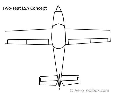
We’ll continue to use this conceptual aircraft, specify an engine and propeller, and then use this information to estimate the variation in thrust produced with speed. By superimposing the thrust and drag variation on the same graph we can estimate the theoretical top speed of our aircraft (the speed at which the available thrust is equal to the drag), and the thrust produced at various power settings.
The aircraft drag variation with velocity that we calculated in Part 9 is plotted below. In Part 9 we did not account for the landing gear when performing the drag calculation. Assuming a conventional fixed landing gear, the drag impact of the gear is added this to the total drag of the aircraft to arrive at the drag plot shown below for the sea level case at a standard atmosphere.
In order to calculate the variation in thrust with airspeed we first must specify an engine and propeller combination. The propeller blade diameter, pitch, and number of blades are important considerations which must be specified in order to determine the thrust produced.
How does an engine and propeller produce thrust?
An internal combustion engine works by converting reciprocating motion (pistons moving in the cylinder) to rotational motion (the rotation of the crankshaft). In this way, the engine supplies rotational energy to the propeller shaft. The propeller in turn transfers this rotational energy into forward thrust through the acceleration of a mass of air approximately equal to the diameter of the propeller through a momentum transfer to the air by the rotation of the propeller. It is the reaction force to this momentum transfer that produces the thrust that propels the aircraft through the air.
It is intuitive that energy must be expended in order for the engine to spin the propeller, and so the available power with which to generate thrust is equal to the total power produced by the engine less that power required to spin the propeller.
We will first look at the engine and propeller separately, and then bring together what we have learnt in order to specify an engine-propeller combination that will work well together on our aircraft. Once the engine-propeller combination is fixed we can calculate our aircraft’s theoretical maximum speed at a number of different power settings.
Let’s start by finding a suitable engine.
Selecting an Engine
In this tutorial we are going to specify our engine based on a cruise requirement. The first step is therefore to estimate the power requirement of our aircraft at our specified cruise speed. At a constant cruise speed, the aircraft forces will be in balance; thus the thrust produced by the engine-propeller combination must be equal to the total drag of the aircraft.
Power is defined as the rate at which work is done, and work is simply a force multiplied by a displacement. Therefore, the total power required to keep our aircraft flying at a constant speed is simply the product of the drag force and velocity.
$$ P_{Req} = Drag \times Velocity$$
Where:
\(P_{Req} = \) Required Power
Multiplying the drag force by flying speed and plotting this through the range of envisioned flying speeds gives us a quick indication of the power required to cruise at different speeds.
We see from the plot above that in order to cruise at 120 knots, our propeller must impart approximately 38.5 kW of power into the air to produce sufficient thrust to overcome the drag generated by the aircraft.
The propeller translates the rotational power available at the shaft to thrust power to push the aircraft forward. During the generation of this power, energy is required to spin the propeller and so the power available at the shaft is never equal to the power that the propeller can supply to the air. The ratio of the power available for thrust generation to that output by the engine shaft is referred to as propeller efficiency. A well-designed propeller operating at its most efficient point has an efficiency of between 0.80 and 0.85 and so the thrust power required above must be factored by the propeller efficiency to determine the shaft engine power required to maintain the chosen cruise speed. If we assume that the selected propeller is designed to be most efficient at the designated cruise speed, then the required engine power is determined as follows:
$$P_{Engine \ Cruise} = \frac{P_{Req}}{\eta}$$
If we assume that the efficiency, \(\eta=0.85\), then we can calculate the engine power required.
$$P_{Engine \ Cruise} = \frac{38.5}{0.85} = 45.3 kW$$
This result shows us that we must specify an engine that produces approximately 45 kW at a cruise power setting. Since 120 kts is at the upper end of our cruise range we will assume that 120 kts indicates a high cruise setting where the engine is producing at least 75 % of its take-off power.
The maximum engine power that the engine should produce is therefore:
$$P_{Max} = \frac{45.3}{0.75} = 60 kW \ (80 HP)$$
We are therefore looking for an engine that is rated at a maximum of 80 hp (60 kW) at sea level.
The requirement for an 80 hp engine shows us that we are on the right track with our drag estimation as light sport aircraft generally are fitted with engines in the 65 – 100 hp range.
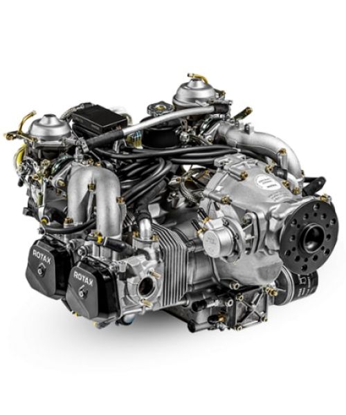
Rotax 912 family
One of the most popular engines in this category is built by the Austrian manufacturer Rotax which produces an 80 hp engine, the Rotax 912 UL. This four-stroke engine displaces 1.21 L or 74 cubic inches and can output a maximum of 59.6 kW (80 hp) at 5800 rpm and 103 Nm (75.9 ft lbs) of torque at 4800 rpm. Since the Rotax family of engines produce their maximum power and torque at relatively high engine speeds, the engines are geared down through a reduction gearbox so that the propeller does not turn at speeds faster than 2400 RPM – 2600 RPM.
The Rotax 912 family of engines is the most popular poweplant choice among recreational aviators. Rotax sold their 50 000th 912 engine in 2014 and produce both a certified and uncertified variant. The engine can be run on leaded or unleaded motor car fuel or even 100 LL Avgas.
The Rotax 912 UL engine is therefore a great fit for our theoretical concept aircraft. We will make use of the standard reduction gear ratio of 2.27 for this example, although the 80 Hp engine can optionally be fitted with a 2.43 reduction gearbox to match its larger 100 Hp sibling the 912 ULS.
The Rotax website has some very useful engine performance data which can be freely downloaded. We’ll use this to build an engine performance model that can help us to determine our aircraft’s theoretical top speed. You can download the Rotax 912 UL engine datasheet here.
We will start our analysis by assuming that the aircraft is flying at sea level and in a standard atmosphere. The power output of a normally aspirated engine such as the Rotax 912 UL is a function of the density of the air entering the intake manifold. Air density decreases as altitude increases, and as such the total power output of the engine decreases. This doesn’t mean that an aircraft’s maximum speed is always reached at sea level as the loss in power is balanced by a corresponding reduction in the total aircraft drag. This occurs as the drag force is also a function of air density.
The variation in engine power of the Rotax 912 UL is plotted below as a function of engine RPM. This is taken directly from the 912 UL brochure. The 45 kW engine output required to balance the drag force at 120 kts is achieved at approximately 4300 RPM which is 75 % of the maximum engine speed of 5800 RPM. Cruise at an engine speed of 4300 RPM therefore represents an initial estimate of our typical cruise condition.
Propeller
Now that we have selected an engine for our aircraft we need to mate our Rotax 912 UL with a suitable propeller. In order to select the most suitable propeller for our concept aircraft we need to first dig into some propeller theory.
The role of a propeller is to transfer the rotational energy generated at the engine crankshaft into forward thrust through the acceleration of a mass of air approximately equal to the diameter of the propeller. There are three primary variables that will influence the resulting thrust generated: the diameter of the propeller, the number of blades, and the angle of the blades relative to the air passing through the blade. We will look at each in more detail after introducing the forces acting on a propeller blade.
Propeller Forces
A propeller blade is essentially a wing with a twisted airfoil section designed to produce aerodynamic forces as a result of the motion of the blade through the air. Whereas a conventional wing on an airplane produces lift and drag proportional to the square of the forward airspeed, a propeller blade will produce forces based on the resultant vector formed between the rotational velocity of the blade (propeller RPM) and the forward velocity of the aircraft.
Since a propeller bade is nothing more than a rotating wing, it will produce lift and drag in the same way as a conventional wing. However, it doesn’t make much sense to describe the resultant forces produced by the propeller in terms of lift and drag (normal and parallel to the helical flight path of the blade), but rather to resolve the forces into components normal to the direction of rotation of the propeller (thrust force) and parallel to the direction of rotation of the propeller (torque force). 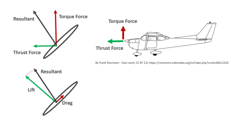
When resolving the forces in terms of thrust and torque force it becomes clear that the lift force contributes both to the thrust and the torque components. The thrust force is dominated by the horizontal component of the lift force while the torque force is primarily a function of the vertical component of the lift generated by the blade. In order to spin the propeller at a constant RPM the engine must produce sufficient torque at the propeller shaft to balance the torque force produced by the rotating propeller.
Propeller Diameter
A propeller works by accelerating a tube of air with a diameter approximately equal to that of the propeller. This results in a reaction thrust force which propels the aircraft forward. The rotation of the propeller adds momentum to the air tube where momentum is equal to the mass of air (function of diameter) multiplied by the rearward velocity.
$$Momentum = Mass \times Velocity$$
This means that by increasing the diameter of the propeller the rearward velocity imparted can be decreased while still preserving the total momentum imparted into the air. The energy expended by the propeller is equal to the kinetic energy imparted from the propeller to the tube of air. Since the total kinetic energy is a function of mass and velocity squared, increasing the mass of air (propeller diameter) is more energy efficient than increasing the velocity of the air for a given energy state.
The conclusion from the above explanation is that it is always most efficient to use the largest propeller blade diameter that an engine can safely accommodate. An old rule of thumb for propeller designers was to “keep it as long as possible, as long as possible”
Remember though that the moment of inertia of the blade increases exponentially with blade diameter and that a larger diameter will also impart exponentially larger gyroscopic loads. This could cause a catastrophic failure of the blade at high rotational speeds. We will discuss the concept of the moment of inertia of a propeller later in this post.
It is also important to remember that the greater the diameter of the blade, the higher the resulting speed at the propeller tip. One limitation on the propeller diameter is therefore that the propeller should never be so large that sonic speeds are reached at the tip when the engine is operating at its maximum RPM.
Another important consideration is the clearance between the tip of the propeller and the ground. The diameter should be specified such that the aircraft can be operated safely when taking-off and landing without the risk of a propeller strike in these critical phases of flight.
Number of Blades
The number of blades, the width (chord), and the diameter of the propeller determine the total blade area. Generally larger engines that produce more power require a greater number of blades to extract that power and convert it into useful thrust. In theory the most efficient propeller blade configuration is actually a single blade design which is counter-balanced by a mass; and thereafter increasing the number of blades leads to slightly less efficient configurations. However, in practice, single bladed propellers don't seem to work particularly well.
Increasing the number of blades reduces cabin noise and vibration. In a single engine aircraft with an engine installed in the nose, each blade creates a pressure pulse on every rotation which may be felt on the windscreen and through the cabin. Assuming a given diameter (constant mass flow) the greater the number of blades, the smaller the pressure pulse that each blade imparts onto the aircraft. A three-bladed propeller will therefore be inherently quieter and smoother than an equivalent two-bladed configuration.
Another important consideration is the diameter of the propeller blade. A larger, more powerful engine requires a greater blade area to extract the maximum thrust for a given power setting. Blade area can be increased either by increasing the diameter of the propeller, increasing the chord of the propeller, or by increasing the number of blades. Increasing the diameter of the blade is preferable but only to a point. A larger diameter blade will result in an increase in the tip speed of the propeller which leads to noise and drag increases as transonic speeds are reached. There are also ground clearance considerations which must be taken into account when increasing the blade diameter. Finally, increasing the chord of the blade may result in an increase in the interaction between the blades as the solidity ratio is increased. This leads to a decrease in efficiency and a reduction in thrust extracted.
Increasing the number of blades therefore becomes the best solution to most efficiently extract the desired thrust from an engine where a propeller with fewer blades is unable to deliver the thrust required.
In the case of our conceptual LSA, either a two-bladed or three-bladed propeller should be chosen. A three-bladed propeller may result in a slightly lower efficiency compared to an identical two-bladed design but improved cabin comfort may necessitate that a three-bladed design be preferable. A three-bladed design has been selected going forward in this tutorial, but an analysis identical to that presented below may be used to determine the thrust of an equivalent two-bladed design should the reader is interested.
Propeller Pitch
Broadly propeller pitch refers to the ease with which the propeller can spin through the air. There are a few different concepts lumped under the term “pitch” which all describe the same phenomenon.
- Pitch refers to the angle of the propeller blade relative to a flat plane.
- Pitch can refer to the distance that the propeller advances through the air during one revolution.
- Pitch can be thought of as the size of the “bite” the propeller takes out of the air.
Pitch is best explained using an analogy to the gearbox in a car. When pulling off from a stationary start, a low gear is selected, which allows the engine to spin up quickly and get the car moving. However, remaining in a low gear for the duration of the drive is very inefficient and will limit the car's top speed, as the engine hits the rev limiter quickly and is unable to supply the power needed to drive at a faster speed. Similarly, trying to pull off in a car from a high gear will stall the engine, as the high gear ratio will limit the ability of the engine to reach a speed where the engine is operating in its power band.
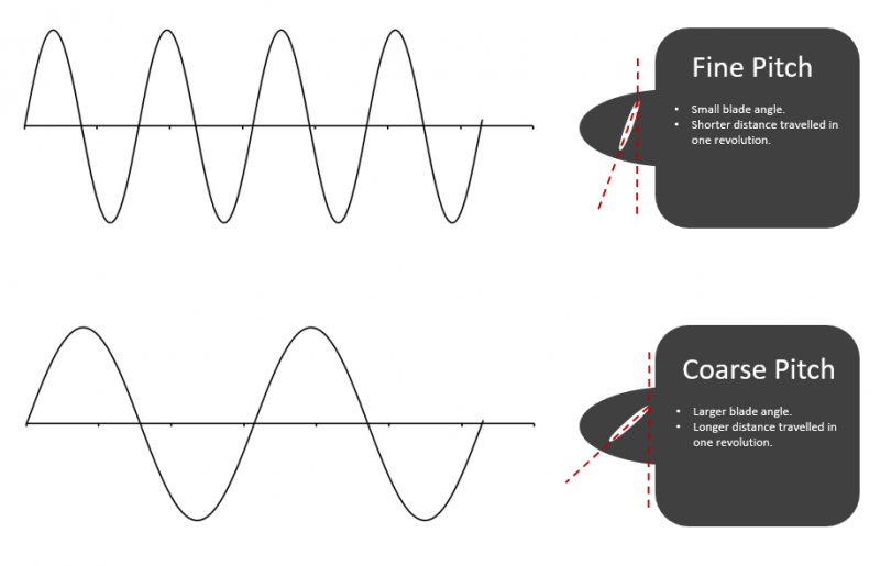
The same can be said for the pitch of a propeller. Instead of gear ratios, we talk about the pitch being either fine (low gear) or coarse (high gear).
A fine pitch propeller will have a low blade angle, will rotate easily without taking a big bite out of the air, and will move forward through the air a short distance every revolution (low advance ratio). This will allow the engine to spin easily and operate at a high speed (rpm).
A coarse pitch propeller will have a high blade angle, will take a large bite out of the air with every turn, and will move forward through the air a large distance every revolution. A coarse pitch setting will limit the speed at which the engine operates.
A propeller blade is really nothing more than a rotating wing and will produce lift and drag forces as it moves through the air.
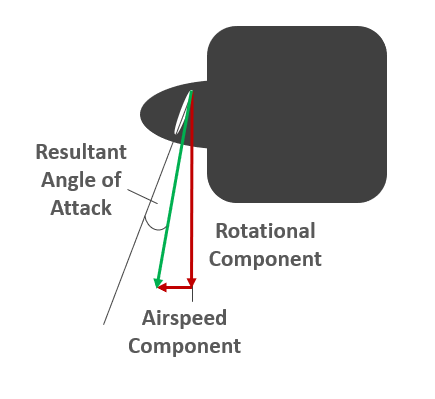
Since a propeller functions in the same way as a wing, the angle of attack that the blade makes with the relative wind will determine how much lift and drag is produced at any given time. The relative wind passing over the propeller blade is a function of both the tangential velocity induced by the rotating blade, and the component of the airspeed in the direction of flight. Defining the angle of attack of the blade as the angle between the chord of the blade and the relative wind vector, it becomes clear that the faster the aircraft is travelling through the air, the lower the effective angle of attack of the blade at a given pitch setting.
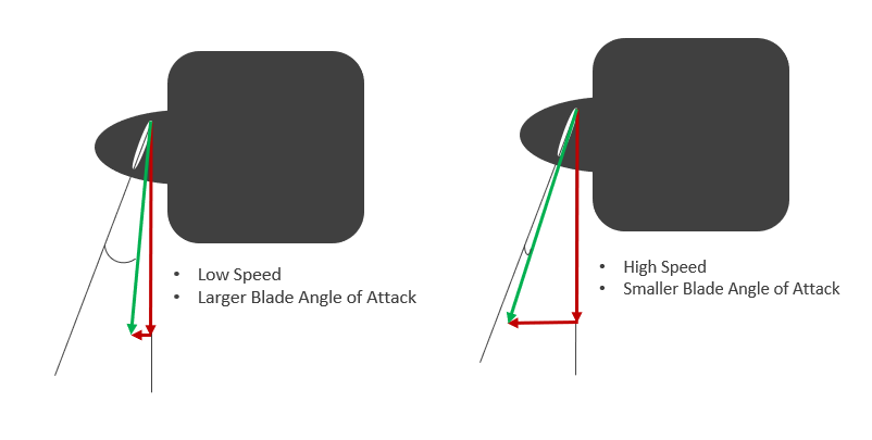
As the blade angle of attack increases, the lift coefficient of the propeller blade increases, and more thrust is produced. Similar to a conventional wing, at some critical angle of attack the blade will stall, with a corresponding drop in thrust.
The resultant angle of attack of the blade can be manipulated by modifying the pitch (blade angle) such that the propeller is always operating in the optimum point of the lift curve. The figure below describes four scenarios of airspeed and propeller pitch configuration. 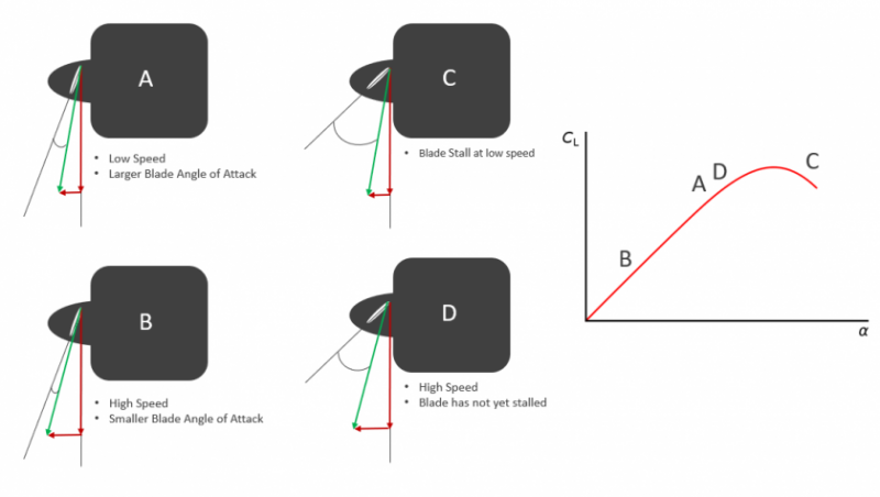
Configuration A is a propeller with a fine pitch (small blade angle) operating at a low speed such that the resultant angle of attack of the blade is in the linear region of the lift curve and the blade is efficiently producing thrust at the low airspeed.
Configuration B shows the blade at the same pitch angle as Configuration A but this time at a higher flying speed. The resultant angle of attack is now much lower than Configuration A and as such the blade will be produce less lift and correspondingly less thrust.
Configuration C shows a blade with a coarser pitch (larger angle) at a low airspeed. The component of the airspeed is not sufficient to reduce the resultant angle of attack of the blade to a point below the stall angle. The blade is therefore stalled and will produce a correspondingly lower thrust.
Configuration D shows a blade in a coarse pitch setting at a high airspeed. In this case the large airspeed component reduces the resultant angle of attack to a point that is within the linear lift region of the lift curve and away from the stall. Here the blade is efficiently producing thrust.
Based on the explanation above we can develop some rules regarding efficient operation of a propeller during the various phases of flight.
- Take-off and landing occur at low speeds and therefore a fine pitch configuration is most preferable to produce the greatest thrust (or to have the greatest possible available thrust in the case of a go-around during landing).
- Cruise is generally flown at relatively high speeds and as such a coarse pitch is the most efficient configuration to generate the thrust required to overcome the cruise drag.
- A climb configuration is most efficient where the pitch is slightly more coarse than during take-off but more fine than in the cruise.
The operating propeller pitch is therefore a crucial driver to the performance of the propeller and the resulting aircraft performance. There are four basic propeller classifications, and all refer to the method by which the propeller pitch is set up or adjusted.
Types of Propellers
Fixed Pitch
This is the simplest propeller type, and as the name suggests the pitch is fixed from the day that the propeller leaves the manufacturer. This results in a propeller which is a compromise between a fine and coarse pitch and limits both the take-off and climb performance (where a fine pitch is preferable) and the cruise performance (where a coarse pitch is desirable).
The propeller may be a compromise but the reduced complexity that a fixed pitch offers results in a much simpler (and therefore cheaper) propeller. It is for these reasons that a fixed pitch propeller is often used on light aircraft where the performance benefits of a more complex propeller are outweighed by the simplicity that the fixed pitch propeller offers. Some examples of aircraft using a fixed pitch propeller include the Cessna 172, Piper PA-28-140 Cherokee, and the Tecnam P-92 Echo.
Some manufacturers will give aircraft operators the option of either a climb propeller (finer pitch) or a cruise propeller (coarser pitch) when purchasing a new propeller.
Ground Adjustable Pitch
As the name implies, this is a fixed pitch propeller that can be adjusted on the ground before a flight to tailor a certain operating environment or mission. Once airborne, the propeller operates at a fixed pitch and is only adjustable once back on the ground.
Variable Pitch
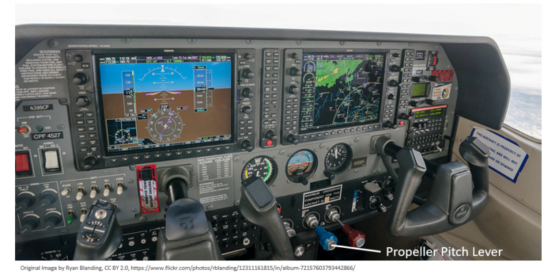
A variable pitch propeller allows the pilot to adjust the blade pitch during flight which means that the propeller/engine combination can be tuned to the most efficient combination to suit the phase of flight. The blade angle on a manually operated inflight-adjustable variable pitch propeller is controlled by the pilot using the pitch lever in the cockpit and allows for a wide range of power settings to be achieved by varying engine power and speed.
A manually operated variable pitch propeller does not make use of a speed governor and so the propeller speed will still vary in a manner similar to a fixed pitch propeller if airspeed, engine rpm and attitude are varied at a given pitch.
Constant Speed Propeller
A constant speed propeller is really just a subset of the variable pitch type. These propellers are fitted with a governor which automatically adjusts the pitch of the blades to keep the rpm constant during flight. A desired propeller speed is set, and the governor ensures that this rpm is maintained regardless of whether the engine power, airspeed, or aircraft attitude is changed.
Selecting a Propeller
With many propeller variables to select from it can be a little overwhelming knowing where to start. Since we are designing a relatively simple aircraft where cost is an important driver, we will go ahead and select a fixed pitch propeller for our concept aircraft. Generally it is good practice to start with the most simple configuration and only add complexity as necessary if the performance requirements can not be met.
We are sizing our engine-propeller combination based on attaining a particular cruise speed (120 kts), so we’ll aim to specify a “cruise prop” which will have a coarser pitch than a corresponding “climb prop”.
As mentioned previously, we should aim for the largest possible propeller that our engine can safely accommodate. We also need to check that the tip speed of the propeller remains away from the transonic region at high engine speeds, and that adequate clearance is maintained between the propeller and the ground during take-off and landing.
Tip Speed
Looking at aircraft of a similar size and performance, the propeller diameter is generally in the region of 1.4 – 1.8 m (4.6 ft to 6.0 ft). We will specify a propeller that falls within this blade length band.
A quick calculation is performed at the largest considered diameter, to ensure that at the tip speed of does not approach sonic speed at the maximum operating RPM the propeller.
The helical propeller tip speed is a function of both the rotational velocity and the translational velocity (airspeed) imparted to the propeller as the aircraft moves through the air.
$$V_{tip-helical} = \sqrt{V_{rot}^2+V_{trans}^2}$$
The rotational tip speed is a function of the propeller speed (specified here in revolutions per second) and the blade diameter.
$$V_{rot} = \pi \times d \times rps $$
The translational velocity is simply the airspeed expressed in the same units as the calculated rotational tip velocity.
$$V_{trans} = airspeed$$
The book “Aircraft Design” by Raymer suggests that the helical tip speed of a wooden propeller should be kept below 850 fps, a metal propeller, 950 fps, and if noise is a concern than on take-off the helical tip speed should be below 700 fps.
The helical tip speed was checked at two different conditions; (i) a dive at full throttle, and (ii) the stall speed at full throttle (40 kts). 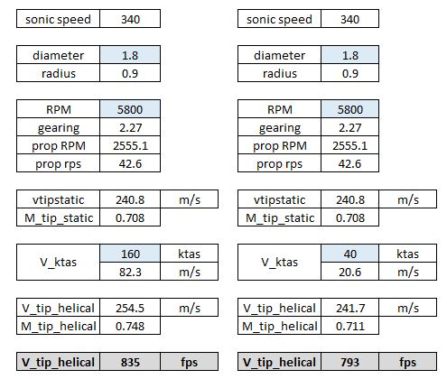
Assuming that the largest considered diameter propeller is used (1.8 m) and that the engine is able to swing the propeller at the maximum engine speed (5800 RPM), the helical tip speed will not exceed 850 fps in a dive. The take-off case shows a tip speed a little higher than recommended but this is not all-together unexpected for a propeller attached to a high revving engine such as a Rotax 912. In practice the Rotax 912 UL is rarely able to reach 5800 RPM during take-off with most propellers fitted, and so the noise should not be a large consideration here.
We can conclude that tip speed will not be a limiting factor in our design.
Propeller Torque
It was mentioned previously that the largest propeller practical should always be specified in order to produce thrust in the most efficient manner. It is important to understand that the larger the propeller, the greater the engine torque required to spin that propeller at the speed necessary to generate the thrust required to sustain the forward motion of our aircraft. It is this torque requirement that often limits the propeller diameter for a given engine.
Newton’s second law states that a body will tend to remain in a state of equilibrium, and only accelerate if acted upon by an unbalanced force. The tendency for a body to return to a state of rest or to resist acceleration can be attributed to the inertia of the body. It is this inertia that must be overcome for the body to be accelerated.
There is an analogous concept to bodies in rotation where the moment of inertia of the body determines the torque required to achieve a certain angular acceleration. Simply put, the larger and heavier the propeller, the greater the torque that must be supplied by the engine in order to spin the propeller at the desired RPM.
$$T = I \alpha$$
Where:
\(T = \) Applied Torque
\(I = \) Moment of Inertia
\(\alpha = \) Angular Acceleration
The Moment of Inertia can be defined as the ratio of the angular momentum of a body to its angular velocity. The best way to visualize this is to think of a figure-skater performing spins on the ice. If she brings her hands closer to her body, her moment of inertia decreases and she is able to spin at a faster rate. As she moves her hands away from her body her moment of inertia increases and her rotational velocity decreases. In the same way, a smaller diameter propeller will rotate at a higher RPM than a larger diameter propeller for a given constant angular momentum.
The moment of inertia is a function of the distribution of the mass relative to the rotational center.
$$I = \frac{L}{\omega} = mr^2$$
Where:
\(I = \) Moment of Inertia
\(L = \) Angular Momentum
\(\omega = \) Angular Velocity
\(m = \) Mass
\(r = \) distance from the rotational axis (propeller hub)
To calculate the moment of inertia of a propeller we must consider the distribution of mass of the propeller with respect to the distance that the mass sits from the center of rotation (propeller hub). The figure below is useful to visualize this:
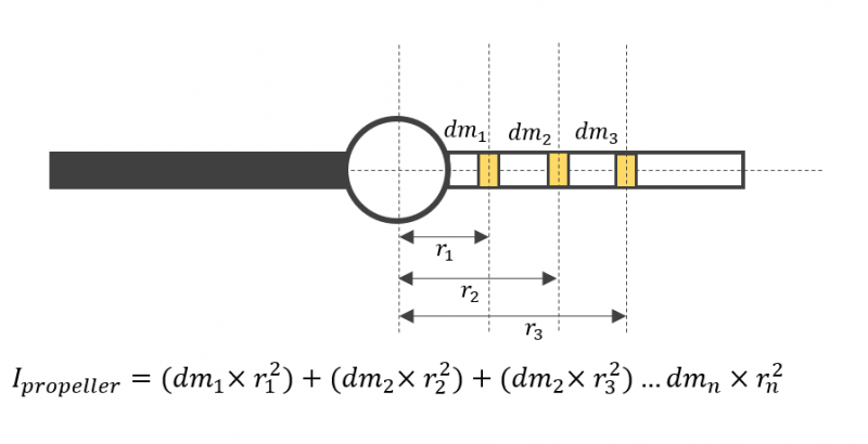
We can think of the propeller as consisting of many little mass elements distributed along the length of each propeller blade. If we sum each of these mass elements and the square of the distance that each element sits away from the hub then we will arrive at a value of the mass moment of inertia of the propeller.
Referring to the equation that defines the moment of inertia, we can conclude that the blade material will have an effect on the \(I = \) value of the propeller. Propellers manufactured from a denser material will have a larger moment of inertia than an equivalent less dense material.
The larger the propeller diameter the further from the hub the center of mass will be located. This will increase the moment of inertia by a factor of the square of the distance, and so a balance must be sought between the largest diameter possible to extract the maximum thrust out of the engine, and the torque requirement of a larger propeller.
The torque required is a function of the moment of inertia and the rotational acceleration of the propeller. In the same way that a certain thrust force must be developed to overcome the drag force of an aircraft to keep the aircraft flying at a constant speed, so must a certain torque be developed to overcome the moment generated by the torque force of the propeller acting at the center of the propeller’s mass as a result of the blades’ rotation through the air.
Rotax publishes an engine torque curve for the 912 UL. Since the engine is geared we need to multiply the engine torque by the gear ratio to determine the torque delivered to the propeller shaft (assuming no losses). The shaft torque available needs to be sufficient to spin the propeller at the range of RPM settings through which the engine operates. The propeller will also accelerate as the throttle setting is adjusted before reaching equilibrium at the new power setting. The engine therefore should supply sufficient torque to allow the propeller to change speeds quickly and easily.
If the moment of inertia of the propeller and the available shaft torque is mis-matched, the engine will not be able to spin the propeller at the required RPM and the engine/propeller will not be able to generate the thrust expected.
We will not manually calculate the moment of inertia of the propeller in this tutorial as we will not go beyond specifying the number of blades, a pitch angle, and diameter for our conceptual LSA. Rotax notes that for safe operation of their engine, no propeller fitted to a 912 UL should have a moment of inertia greater than \(0.6 \ kg.m^2\).
Typical blades fitted to an LSA of this size have moment of inertias in the region of \(0.3 – 0.6 \ kg.m^2\). We will assume that our aircraft is no exception and that the torque output from the engine is sufficient to safely operate any propeller that we select.
Propeller Charts
When designing a new propeller, manufacturers will generate a data set which among other variables charts the propeller efficiency against a dimensionless parameter known as the advance ratio. This is done for each propeller configuration; i.e. this will be charted for a set of pitch angles and number of blades. These propeller charts can then be used to select a propeller based on three criteria; number of blades, pitch, and diameter.
The propeller advance ratio is defined as the ratio of the freestream fluid speed (airspeed) to the propeller tip speed. It is a useful non-dimensional property used in propeller theory as the propeller will experience the same angle of attack at each blade section at a given advance ratio irrespective of the forward speed of the aircraft or the rotational speed of the propeller.
It is a simple parameter to calculate as it is a function of the airspeed, the rotational speed of the propeller and diameter.
$$J = \frac{V}{nd}$$
Where:
\(J = \) Dimensionless Advance Ratio
\(n = \) propeller speed (rev/s)
\(d = \) Propeller Diameter
Since we are sizing our propeller for cruise, we would like to try and achieve the maximum propeller efficiency at our designated cruise speed. We will however need to be aware that with a fixed pitch propeller a compromise between a coarse pitch for cruise and a fine pitch for take-off and landing must be made.
The manufacturer’s propeller charts are generally not published and publicly available, but this shouldn’t stop us sizing our propeller for this tutorial. We will use the charts generated in NACA Report No. 640 to size our propeller.
Note: this is an old NACA report which is unclassified and freely available to download and use. The report was generated in the late 1930’s and advances in propeller technology are likely to have produced propellers far better suited to the light sport market than this particular configuration. Nevertheless the propeller charts in the report are very useful as a teaching tool to demonstrate how to specify and design a propeller as well as to clearly show the limitations inherent in a fixed pitch configuration.
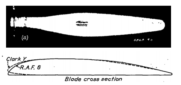
The NACA report details a comprehensive study of seven propeller configurations built and tested in the N.A.C.A 20-ft wind tunnel. We’ll make use of the Clark Y profile tested and limit our analysis to a three-bladed design for this tutorial. If you are trying to design an engine-propeller configuration for a real aircraft you should contact the propeller manufacturer and ask for the charts specific to their design rather than just use an unclassified NACA report.
Below is the propeller chart extracted from NACA Report No. 640 for the three-bladed Clark Y configuration. The advance ratio is plotted on the x-axis and the resulting efficiency on the y-axis for a range of blade angles from 15° to 45°.
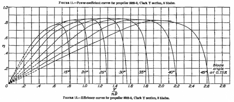
The best way to size the propeller is to perform a sensitivity study around the three variables that we have identified; namely the diameter of the propeller, the blade pitch and the number of blades. We’ll limit our discussion to diameter and blade pitch in this tutorial simply so that we only use one propeller chart. If you wanted to compare the effect of a three-bladed prop to a two bladed one you could extract a second chart from the NACA report and perform the same analysis. The easiest way to perform a sensitivity study is to digitize the propeller chart and then use that information to build a small model of our engine and propeller combination. I like to use the Engauge Digitizer which is open-source software to quickly digitize the graph.
I have extracted three pitch angles from the graph above; 20°, 25°, and 30°.
Let’s calculate the advance ratio at an engine speed of 4300 RPM and a propeller diameter of 1.70 m (approximately 5.7 inches) with the aircraft flying at 120 knots.
$$V = 120 \ kts = 120\times0.51444 = 61.73 \ m.s^{-1}$$ $$4300 \ RPM = \frac{4300}{60} = 71.67 \ rps$$
The propeller shaft is geared down by a ratio of 2.27.
$$rps_{prop} = \frac{71.67}{2.27}=31.6 \ rps$$
The advance ratio follows:
$$J = \frac{V}{nd} = \frac{61.73}{31.6\times1.7} = 1.15$$
The advance ratio is a non-dimensional calculation so provided a consistent set of units is used it won’t matter whether the calculation is performed in SI units as above or using imperial units.
Looking at the prop chart digitized above we see that the efficiency differs at each of the three pitch angles. Since we are optimizing for cruise we would like the pitch angle to provide the greatest possible efficiency. The four efficiencies calculated at an advance ratio of 1.15 are shown in the table below.
| Blade Pitch | Efficiency |
|---|---|
| 20° | NaN |
| 25° | 0.816 |
| 30° | 0.836 |
Looking at the table above a quick conclusion may be that the blade angle should be 30° as this is the angle that produces the greatest efficiency. However, before we can freeze our blade angle it would be wise to run through a similar exercise through the range of speeds that the aircraft is expected to fly.
Calculating Thrust
Most importantly, we need to quantify the effect of the larger blade pitch on the thrust produced at speeds below cruise. Recall that the larger (coarser) blade pitch will allow the aircraft to take a bigger bite out of the air which makes it more efficient at higher speeds. Unfortunately, this means that at lower speeds (take-off and climb) the advance ratio is lower also; resulting in low efficiencies as the propeller/engine combination is unable to effectively generate thrust. Recall that at low speeds the effective angle of attack of a coarse propeller blade may be greater than the stall angle resulting in low efficiencies and a corresponding reduction in thrust.
The efficiency is used directly in the calculation of the available thrust making use of the relationship between power, force, and velocity:
$$P_{shaft} = F_{thrust}\times V$$
$$P_{shaft} = P_{engine}\times \eta$$
The thrust follows:
$$F_{thrust} = \frac{P_{engine}\times \eta}{V}$$
Calculate the thrust produced at 4300 RPM (engine setting) at a pitch angle of 25°, and flying at 120 kts:
$$F_{thrust} = \frac{45.2\times 1000\times 0.816}{61.7}= 598 \ N$$
Since we are working in SI units you must convert the airspeed from \(kts\) to \(m.s^1\) and \(kW\) to \(W\).
This calculation (determining advance ratio, efficiency, and thrust) should be performed through a range of flying speeds in order to assist in selecting a pitch angle that will provide a compromise between the desire to cruise at high speeds and the ability to safely take off and climb.
This is performed at two engine settings: 4300 RPM and 5000 RPM and plotted on the same curve as the aircraft drag variation in order to determine theoretical aircraft top speed (Thrust = Drag) at each engine setting.
The results show clearly the effect of varying blade pitch in both the slow-speed and high-speed flight regimes. At 5000 RPM (close to full throttle), all three pitch angles produce a top speed in excess of 120 knots. It is interesting that at 120 knots, the highest efficiency is seen using the 25° pitch configuration and not the coarser 30° pitched blade. The coarser blade only reaches peak efficiency at a greater advance ratio outside of the desired speed range of our conceptual aircraft.
If maximum speed was the only consideration then a fixed blade pitch of 25° should be selected. However, the coarser pitch results in blade stall at low speed with a corresponding drop in thrust available during the take-off. At 50 knots the coarser 25° propeller would only be producing 84% of the thrust of the 20° pitch propeller and 69% at 10 knots. This would have an enormous impact on the take-off performance of the proposed aircraft, limiting the airfields the aircraft could operate from, and potentially putting the pilot into a dangerous situation when attempting a go-around in a high drag and low speed configuration.
By normalizing the thrust output at each pitch with the output from the 20° pitch case and plotting this against airspeed, the loss in thrust at low speed with increasingly coarser pitches is well demonstrated. At higher speeds the increase in thrust produced by the coarser blade angle at higher speeds is also well demonstrated.
This provides a clear illustration why when flying an aircraft with a variable pitch propeller the pilot will always ensure the pitch is set to fully fine as a part of the downwind landing checks in order to maximize the thrust available should the pilot need to perform a go-around.
The case where the engine RPM is set to 4300 produces a similar set of results. Here a theoretical top speed of just less than 120 knots is attainable if the pitch is set to 25° but as discussed, the impact on the thrust produced at low speed is too severe to select this configuration.
Final Configuration
Based on the results presented above the optimum configuration for our fixed pitch conceptual LSA would be to make use of a 20° blade angle and a three-bladed configuration with a diameter of 1.70 m (5 ft 7’’). This should provide a good balance between the desired high-speed cruise performance and the need for sufficient thrust at low speed to safely operate the aircraft during take-off, climb, and landing.
The final configuration is summarized below:
| Engine | Rotax 912 UL |
| Reduction Gear Ratio | 2.27 |
| Propeller Diameter | 1.70 m (5 ft 7'') |
| No. Blades | 3 |
| Pitch Angle | 20° |
| Max Speed @ 5000 RPM (SL ISA) | 120 KTAS |
| Max Speed @ 4300 RPM (SL ISA) | 105 KTAS |
In this tutorial we have sized the propeller and engine using the cruise speed requirement as a constraint. Further work to determine the take-off performance of the engine-propeller combination should be completed before the configuration is frozen. Typically the aircraft designer will have a take-off performance requirement in addition to a cruise requirement and an exercise similar to that above would be completed to determine whether the take-off requirement could be met. Invariably some compromise between the take-off and landing constraint would then be made in the final specification.
This tutorial concludes the 10 part series on an introduction to aircraft design and specification. For further reading, or to catch up on any tutorials missed, you can find the rest of the series here.
If you enjoyed this series or found the tutorials useful then please share them on your favorite social media platform! Thanks for reading.


