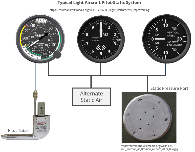
This post is a part of our series on aircraft instrumentation and is dedicated to the airspeed indicator (ASI). This is an instrument that makes use of the aircraft’s pitot-static system which was introduced in the previous post to provide the pilot with a real time readout of the aircraft's airspeed.
How the Airspeed Indicator Works
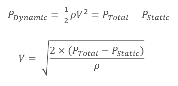
Dynamic Pressure
The airspeed indicator is a pressure instrument and requires both a pitot pressure (total pressure) and a static pressure measurement to operate correctly.
The basis of operation is relatively simple; by subtracting the static pressure from the total pressure, the dynamic pressure is obtained which is a function of velocity in accordance with Bernoulli’s equation.
It is important to note that the resulting velocity is a function of the air density. Since the pitot-static system does not output a real-time air density, the instrument is calibrated to sea level density on a standard atmospheric day. The air density varies with altitude and temperature so the ASI will only read the true airspeed if the aircraft is operating in the idealised standard day conditions. This is very rarely the case and so the indicated airspeed (reading seen on the instrument) differs from the true airspeed under almost all conditions. This is discussed further below in the section on airspeeds.
Instrument Construction
Traditionally, airspeed indictors were mechanical analogue instruments. We will first discuss how these mechanical instruments are constructed before briefly touching on the more modern digital airspeed readouts seen in glass cockpits.
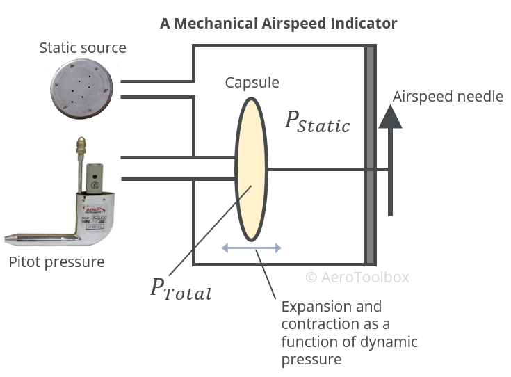
The body of a mechanical airspeed indicator consists of a completely sealed case into which the static pressure line is ported. The inside of the case is therefore maintained at the ambient atmospheric pressure.
A capsule or diaphragm inside the instrument housing is connected to the pitot-pressure line. Since the pitot probe measures the total pressure (dynamic and static pressure) and the instrument housing is kept at the static pressure, the pressure differential between the capsule and the case represents the dynamic pressure. The capsule will then expand and contract with the changing dynamic pressure. A mechanical linkage from the capsule to the instrument face displays this changing dynamic pressure as an airspeed on the dial. The airspeed indicator must be calibrated in order to fix the relationship between the dynamic pressure and the resulting velocity. This calibration is performed at sea level conditions representing a standard day. The ASI always outputs the indicated airspeed which may differ from the true airspeed depending on the prevailing atmospheric conditions.
Modern digital airspeed indicators work using the same basic principles. The airspeed is determined digitally using pressure transducers that convert the resulting pressures into digital signals (usually voltages). These signals are subtracted to provide a measure of the dynamic pressure. A calibration exercise then follows to define a relationship between the resulting voltage output and the airspeed. A digital airspeed indicator will still output the primary airspeed reading as an indicated airspeed but may also show the true airspeed using a mathematical model to determine the ambient air density; a function of temperature and altitude, both available in the cockpit.
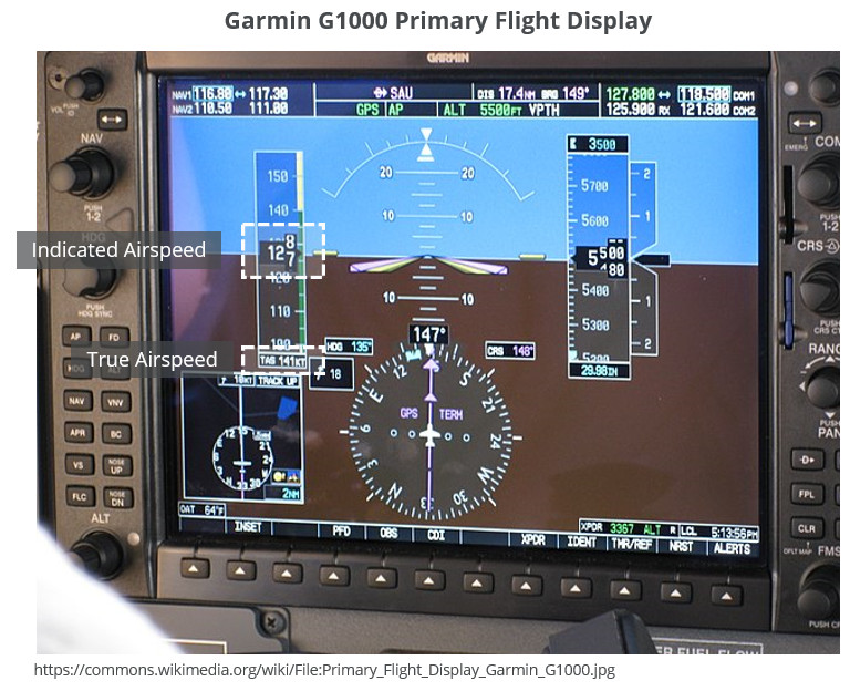
Interpreting the Airspeed Indicator
Colored Markings
Airspeed indicators are marked in accordance with a standard color-coded marking system to enable a pilot to determine at a glance the current airspeed in relation to a number of critical airspeeds that determine the safe operation of the aircraft.
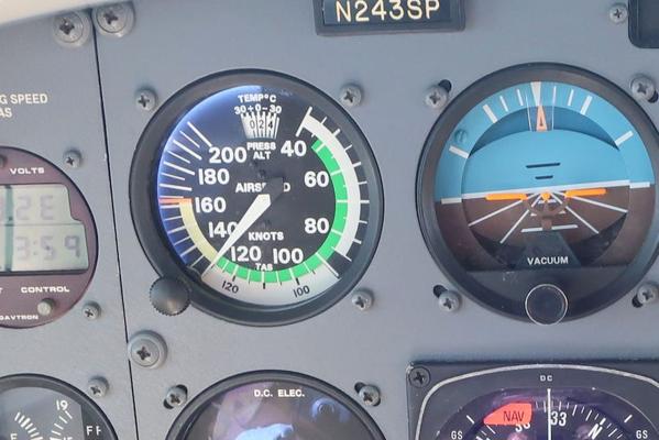
Shown below is a representation of a typical ASI seen on a single-engined light aircraft.
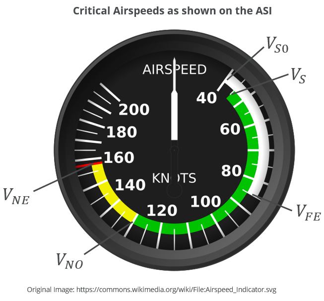
The white arc represents the flap operating range.
- The limits of the white arc represent the maximum flap extension speed \(V_{FE}\) at 85 KIAS and,
- the stall speed with flaps extended in the landing configuration \(V_{S0}\) at 40 KIAS.
The green arc represents the normal operating speed range and it is expected that the bulk of flying operations will occur at these speeds.
- The upper limit of this arc represents the maximum structural cruising speed \(V_{N0}\) which should not be exceeded unless the aircraft is operating in smooth air.
- The lower limit represents the aircraft stall speed in a pre-defined configuration \(V_{S}\). This is usually a power-off stall at maximum take-off weight in a clean configuration (flaps retracted, landing gear stowed).
The yellow arc represents the caution speed range. Operation is permitted in this range but only in smooth air and with caution.
The red line is the never exceed speed and represents the speed above which operation may result in structural failure of the airframe.
Airspeeds
Indicated Airspeed
Using the simplified Bernoulli equation to calculate the flying velocity from the dynamic pressure requires that the air density be known. Since the air density varies with temperature and altitude the airspeed indicator is calibrated to a single condition based on the International Standard Atmosphere model. This is a mathematical model of the atmosphere which is used as a common reference for temperature and pressure measurements at various altitudes from sea level to approximately 80 km above mean sea level. That single condition is defined as a standard sea level day and corresponds to:
- Temperature of +15°C or 59°F
- Static Pressure of 1013.25 hPa or 29.92 inHg
- Density of 1.225 \(kg/m^3\)
- Temperature lapse rate (rate of change of temperature with altitude) that decreases by 1.98°C/1000 ft up to 36 090 ft.
AeroToolbox has a standard atmosphere calculator that you can play around with to get a better feel for how the ambient atmospheric conditions affect the temperature, pressure and density of the air.
The airspeed indicator therefore displays an indicated airspeed which will differ from the true airspeed as soon as the ambient atmospheric conditions deviate from the standard day described above. In cases where the density is lower than the standard day sea level density the indicated airspeed will be lower than the true airspeed.
Indicated airspeed is actually of more use to a pilot than the true airspeed. This is because an aircraft will always stall at the same indicated airspeed (for a given configuration) even though the true airspeed may differ. This occurs because the loading on the airframe structure is a function of the dynamic pressure which is measured directly by the ASI. This means that the aircraft will behave the same way for a given dynamic pressure regardless of the true airspeed, the outside air temperature, or the altitude.
Calibrated Airspeed
This is also sometimes referred to as rectified airspeed and is the indicated airspeed corrected for position and instrumentation error. Aircraft designers always try to position the pitot tube in an area of largely undisturbed airflow. However, local curvatures (for example under the wing where many pitot probes are located) will tend to accelerate or decelerate the air before it enters the probe, changing the dynamic pressure and distorting the airspeed reading. The calibrated airspeed is the indicated airspeed corrected for this error. In practise the differences between calibrated airspeed (CAS) and indicated airspeed (IAS) on a light aircraft are usually small but calibrated airspeed should be used if trying to calculate a more accurate true airspeed.
True Airspeed
True airspeed is the speed that the aircraft travels relative to the mass of air in which it is flying. It is the calibrated airspeed corrected for compressibility effects (negligible if flying below Mach 0.3) and density effects.
As an aircraft climbs the air density will drop which according to the Bernoulli equation will result in the airspeed increasing for a given dynamic pressure. Since the density is fixed on the ASI, the indicated airspeed will always be lower than the true airspeed at higher altitudes. Temperature also plays an important role in the true airspeed: hotter temperatures result in a decrease in density which has the same effect as flying at greater altitudes.
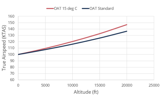
AeroToolbox has a very popular airspeed calculator which you are encouraged to play with to get a better sense of the effect that altitude and temperature has on airspeed. As an example, below is a plot of the variation in true airspeed with altitude where the indicated airspeed is 100 KIAS.
In one plot the temperature is assumed to remain at 15°C from sea level to 20 000 ft, and in the other the atmosphere cools at the standard rate.
100 KIAS at 10 000 ft results in a true airspeed in the region of 120 knots which is a 20% increase over the indicated value. This demonstrates why it is advantageous to cruise at higher altitudes where the air is less dense and the drag lower.
Blockages and Serviceability
Blockages
Since the airspeed indicator is fed pressure from the static and pitot probe, a blockage of either system would result in erroneous airspeed readings that could result in a particularly dangerous situation, especially if the effect of the blockage is not well understood by the pilot.
In level flight, a blockage of the static port will not affect the airspeed reading while the aircraft maintains altitude. This is because the static pressure component of the pitot pressure will remain equal to the blocked static pressure trapped in the static line.
If the pitot pressure line develops a leak, then the pressure in the line will tend to atmospheric (static pressure) and the airspeed indicator will read zero.
Climbing and Descending
A favorite exam question is to determine the effect on the ASI if either the pitot line or the static line becomes blocked during climbing or descending. While some find this a challenging question to answer, it is not too difficult when one understands the mathematical formulation of the airspeed and draws out what is happening in each scenario.
If we take a blocked static port during a constant speed climb for example, the static component of the pitot pressure will drop as the aircraft climbs, but the static port component will remain at the higher pressure of the lower altitude. The resulting pressure differential fed to the instrument will be lower than expected and so the airspeed indicator will under-read.
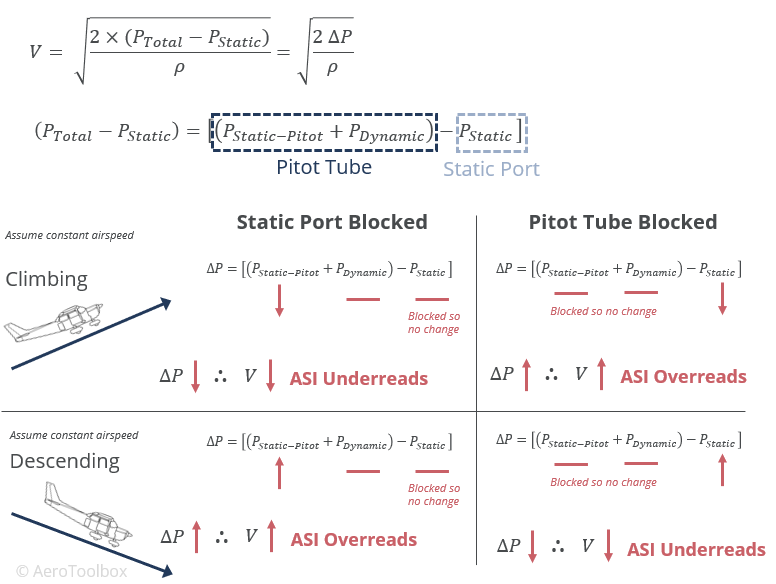
A blocked static port on a descent will cause the pressure differential seen by the instrument to be greater than it should be (static pressure in the instrument remains lower from the higher altitude) and consequently the ASI will over-read.
Instrument Serviceability
A careful prefight inspection should always be undertaken before getting airborne. Check that there are no obvious blockages of either the static port or the pitot tube. You should never blow into the pitot tube when performing the inspection as this could damage the probe.
As the aircraft accelerates down the runway, the pilot should check that the airspeed indicator is working and confirm this with a verbal callout. If the aircraft is accelerating and the airspeed indicator is not registering the increasing speed, then the take-off should be aborted if it is safe to do so. Flying an aircraft without a functioning ASI is dangerous; particularly if you are an inexperienced pilot as the aircraft could slow and stall without the pilot realizing (especially in busy situations like during a circuit to land).


