This article forms a part of our series on aircraft instrumentation and focuses specifically on the altimeter. The altimeter is a pressure instrument used in the cockpit to measure vertical height, and is one of the components that make up an aircraft’s pitot-static system.
How an Altimeter Works
Static Pressure and Standard Atmosphere
An altimeter is essentially an aneroid barometer that is calibrated to measure altitude rather than pressure. Pressure is fed to the instrument through the static pressure port mounted on the side of the aircraft, so that the altimeter continuously reads the ambient static pressure. The static pressure varies as the aircraft climbs or descends, which is indicated on the instrument as a change in altitude.
The relationship between pressure and altitude is determined by a mathematical model of the atmosphere, the International Standard Atmosphere (ISA). This is an idealized model, meaning that a number of assumptions are built in which should be properly understood to correctly use the instrument.
Principally, the model defines a standard set of sea level conditions, and a lapse rate which defines the rate at which the static pressure varies with altitude in the standard atmosphere.
A standard sea level day is defined as:
- Pressure: 1013.25 hPa or 29.92 inHg
- Temperature: 15 °C or 59 °F
- Pressure Lapse Rate: Approximately 1 hPa per 30 ft or 1 inHg per 1000 ft
Since it is very rare for the actual atmospheric conditions to match the standard day conditions perfectly, every aviation altimeter is built with a means to adjust the set point in order that sufficiently accurate altitude readings can be obtained for a wide range of operating conditions.
Provided all pilots operating in a region are flying on the same altimeter setting, adequate vertical spacing should be maintained even if the altitude displayed on the instrument is slightly different to the actual altitude of each aircraft (the altimeter doesn’t correct for atmospheric temperature variations and the pressure lapse rate is assumed).
Altimeter Construction
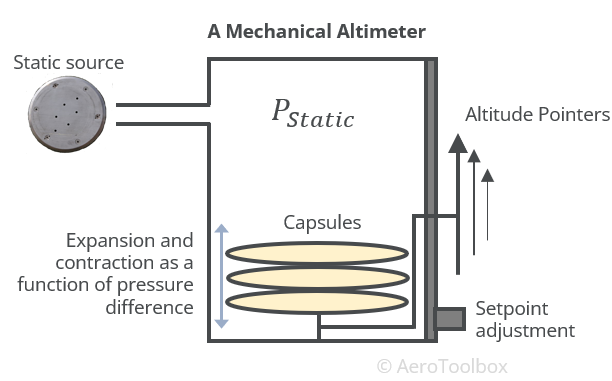
A traditional altimeter fitted to an aircraft is a mechanical instrument comprising a sealed case into which the ambient static pressure is fed. Within the case is a capsule under a partial vacuum that expands or contracts as the ambient pressure changes. The capsule is connected to the dial on the front of the instrument, and is calibrated to display any change in pressure as a change in altitude.
Aircraft altimeters must be accurate to within tens of feet and so are typically designed with three capsules under differing vacuum to indicate the altitude in 10 000 ft, 1000 ft, and 100 ft increments.
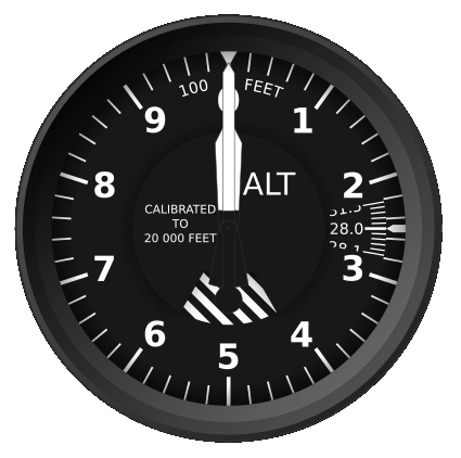
The face of the instrument resembles a clockface with ten altitude increments and three pointers (think hands of a clock) corresponding to the three altitude increments measured (10 000 ft, 1000 ft, 100 ft).

Reading the Altimeter
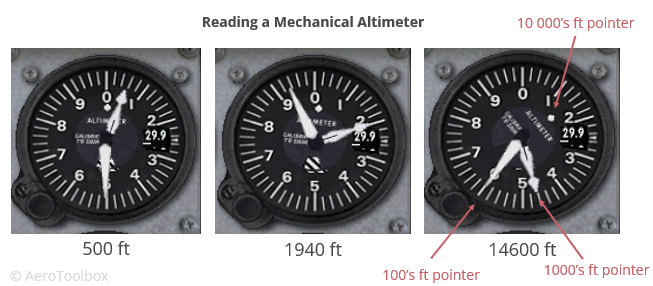
To read an altimeter you must first identify the three pointers on the dial which represents the altitude increments in 10 000 ft, 1000 ft and 100 ft intervals. The pointers representing 100’s of feet and 1000’s of feet can be thought of as similar to the minute and hour hand of a clock. The longest, thinnest pointer (minute hand) represents the altitude increment in 100’s of feet and the shorter, fatter pointer (hour hand) counts 1000’s of feet. The 10 000 ft pointer only becomes relevant once the aircraft reaches and exceeds 10 000 ft in altitude.
Three examples showing differing altitude readouts on a traditional altimeter are shown below.
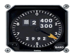
Some aircraft are fitted with a drum-type altimeter which in addition to pointers displays the altitude numerically, similar to an odometer in a motor vehicle. This makes it easier for the pilot to read off the current altitude at a glance.
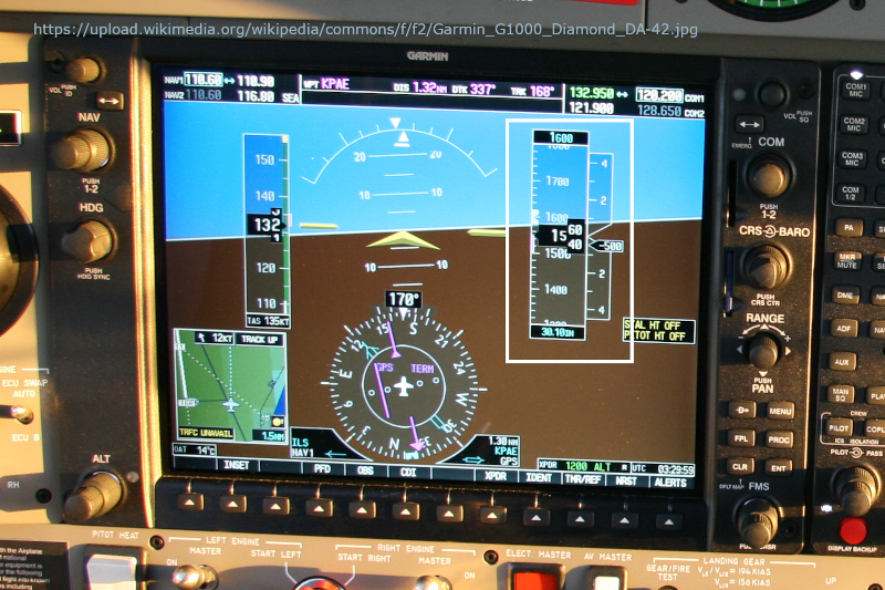
The digitization of cockpits over the last two decades means that if you are flying a newer general aviation aircraft you may not even use a traditional mechanical altimeter as your primary altitude reference. The example below is from a Garmin G1000 and shows a digital altimeter (highlighted with a white border) incorporated into the primary flight display (PFD).
Setting the Altimeter
An altimeter always measures height above a particular pressure datum based on a predefined relationship between pressure and altitude. That relationship is defined as approximately a 1 hPa drop in pressure for ever 30 ft in altitude gained. This is equivalent to a 1 inHg change for every 1000 ft in altitude gain.
The altimeter is only able to measure the current static pressure, which then is related to an altitude via the idealized International Standard Atmosphere mathematical model. Since the relationship between altitude and pressure is assumed, a set point or datum must be selected on the altimeter so that the difference in pressure between the set point and current static pressure can be interpreted as an accurate altitude reading.
The standard atmosphere model assumes that the pressure at sea level is equal to 1013.25 hPa or 29.92 inHg and that the temperature is 15°C. Since this is rarely the case, the altimeter is designed with a knob to adjust the datum pressure in order to correct the current altitude for local atmospheric effects.
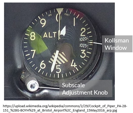
Located at the 3 o’clock position on a traditional mechanical altimeter is the Kollsman window. Adjusting the altimeter changes the value in the Kollsman window which corresponds to the datum pressure being set (either displayed in hPa or inHg depending on whether you are in Europe or the US).
Different setpoint values input into the altimeter will provide the pilot with different reference heights or altitudes. There are a number of Q-codes used in aviation; two are directly applicable to setting the altimeter.
QFE
QFE is the barometric pressure at the airfield in question. If you set the altimeter adjustment knob to QFE, the reading on the altimeter will be the height of the aircraft above a reference point on that airfield (zero on the ground). Conversely, if you adjust the altimeter until the altimeter reads zero while on the ground then you have determined the current atmospheric barometric pressure at the airfield (refer to the value in the Kollsman window).
QNH
QNH is the barometric pressure at the airfield computed to mean sea level using the standard atmosphere model. Setting the subscale knob to QNH will show the altitude of the aircraft above mean sea level. If the airport elevation above mean sea level is known, then you can adjust the altimeter until this value is shown on the instrument, and read off the corresponding QNH in the Kollsman window.
Pressure and Density Altitude
Pressure Altitude
The pressure altitude is the value indicated on the altimeter when 1013 mb or 29.92 inHg (standard sea level pressure) is selected on the subscale. When flying above a given transition altitude you will be assigned a flight level rather than an altitude to maintain. When assigned a flight level you always set the altimeter subscale to 1013 mb or 29.92 inHg. One flight level is equivalent to 100 ft, i.e. FL 100 is 10 000 ft and FL 320 is 32 000 ft.
Since the pressure lapse rate is approximately 1 hPa per 30 ft, the pressure altitude at an airfield can be easily determined if the QNH is known (see here for further details and a calculator).
To convert from airfield elevation to a pressure altitude when the current QNH is known:
$$ \textnormal{PA}_{hPa} \approx \left( 1013.25 - QNH_{hPa} \right) \times 30 ft + \textnormal{field elevation} $$
If the QNH is given in inches of mercury:
$$ \textnormal{PA}_{inHg} \approx \left( 29.92 - QNH_{inHg} \right) \times 1000 ft + \textnormal{field elevation} $$
Density Altitude
Density altitude is the pressure altitude corrected for non-standard temperature. This is equivalent to the altitude in the standard atmosphere model corresponding to the current ambient air density.
Density altitude is a very important parameter when assessing aircraft performance as hotter temperatures are associated with lower air density, and correspondingly poorer aircraft performance. Higher density altitudes are associated with a loss in engine power and reduction in lift generated by the wing. This is most critical during the take-off roll and so should always be considered before departing – especially when heavily laden on a hot day at a high airport elevation.
Density altitude can be approximated when the pressure altitude and current temperature is known along with the ISA temperature corresponding to the airport elevation in question.
$$ \textnormal{DA} \approx \textnormal{PA} + 120 \left ( T - T_{ISA} \right) $$
Where:
\( T \) is the current Outside Air Temperature in °C.
\( T_{ISA} \) is the standard temperature at the given airport elevation in °C.
The variation in standard temperature with altitude can be approximated between sea level and 36 000 ft by the following equation:
$$ T_{ISA} \approx 15 - \left( 0.00198 \times \textnormal{PA} \right) $$
AeroToolbox has a Pressure and Density Altitude Calculator to quickly and accurately determine density altitude from the airport elevation, outside air temperature and airport QNH.
Instrument Errors
There are a few potential sources of error to be aware of when operating an aircraft altimeter.
The first is a position error which is a function of the placement of the static port on the outside of the aircraft. The input static pressure may vary slightly from the actual static pressure depending on the geometry of the aircraft and the location of the port. A calibration card may be prepared which states the altimeter reading offset. This is the same type of error that is manifest on the airspeed indicator as the difference between indicated and calibrated airspeed but is usually small enough to be negligible.
Changes in static pressure as a result of a rapid climb or descent can cause the altimeter to lead or lag slightly.
- Rapid climbs can tend the altimeter to under read (moving from more dense air to less dense air).
- Rapid descents can tend the altimeter to over read (moving into more dense air from less dense air).
This under or over read will correct itself once the aircraft's rate of ascent or descent reduces.
Blockages and leaks in the system can cause erroneous readings on the altimeter. A blockage will keep the altimeter from registering any changes in altitude as the aircraft climbs or descends. A leak in the static line may manifest as a slight overread due to a drop in pressure along the line.


