This post will introduce the aircraft pitot static system which provides pressure readings to the three pressure-based primary flight instruments: the airspeed indicator, the altimeter, and the vertical speed indicator. The system works according to Bernoulli’s equation which relates pressure and velocity. Central to understanding how these instruments work are the concepts of static pressure, total pressure, and dynamic pressure which are discussed in detail.
Introduction
Primary Flight Instruments
A typical light aircraft has six primary flight instruments providing the pilot with data relating to the flight situation of the aircraft. The six instruments are usually laid out directly in front of the pilot for easy reference and consist of an airspeed indicator, attitude indicator, altimeter, turn coordinator, direction indicator, and vertical speed indicator.
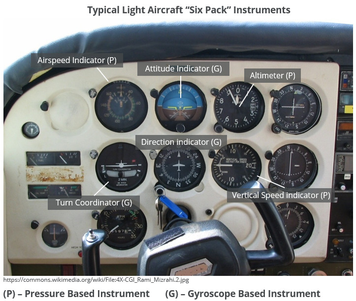
Each of these instruments will be described in more detail in their own post but at this stage it is important to differentiate between instruments that operate based on pressure measurement and instruments that operate based on gyroscopic principles. We will focus on pressure-based instruments now and will tackle gyroscope-based instruments in a separate series of posts.
Pressure Measurement in an Aircraft
Pressure measurement is used to determine airspeed, altitude, and the rate at which altitude is changing (vertical speed). To understand how pressure relates to these flight conditions we need to revise Bernoulli’s equation which relates Total Pressure to Static and Dynamic Pressure.
An aircraft’s pitot-static system measures total pressure and static pressure separately, from which dynamic pressure can be easily calculated by applying Bernoulli’s equation.
Bernoulli’s Equation
Bernoulli’s equation is used in fluid dynamics to relate the speed at which a fluid is moving to that fluid’s static pressure and potential energy. It is most commonly stated in equation form for an incompressible flow (density remains constant) where the relationship between pressure and velocity is determined.
The total pressure at any point in an incompressible and irrotational flow (aircraft moving through the air at a speed below Mach 0.3) is the sum of the static and dynamic pressure components. The pressure head term \(\rho g h\) is small relative to the other two pressure components and can be neglected.
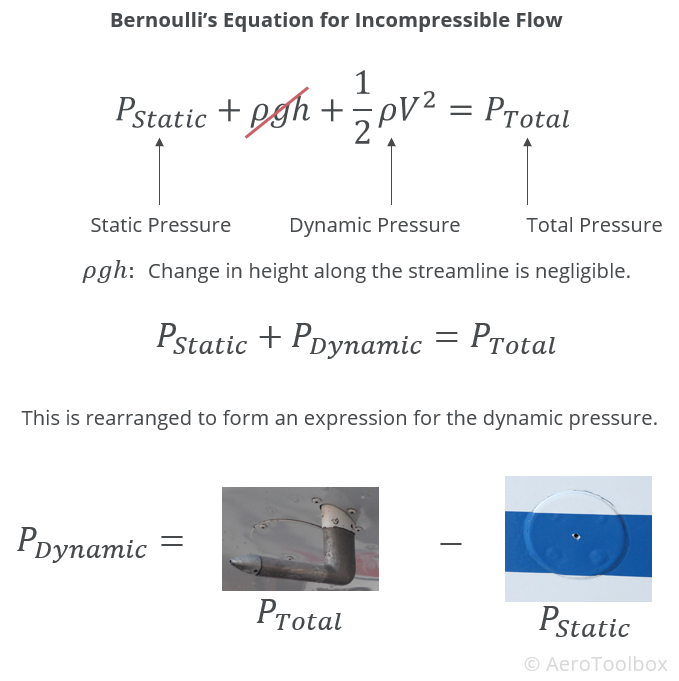
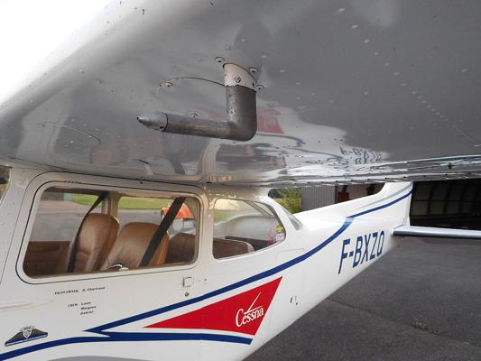
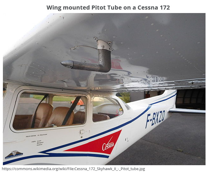
An aircraft has a pitot probe (often located under the wing) to measure the total pressure, and a static port (usually located on the forward fuselage) to measure the static pressure. The dynamic pressure is determined by subtracting the static pressure from the total pressure. The aircraft’s velocity is a function of the dynamic pressure and can be determined by rearranging Bernoulli’s equation and solving for the velocity.
Pitot (Total) Pressure
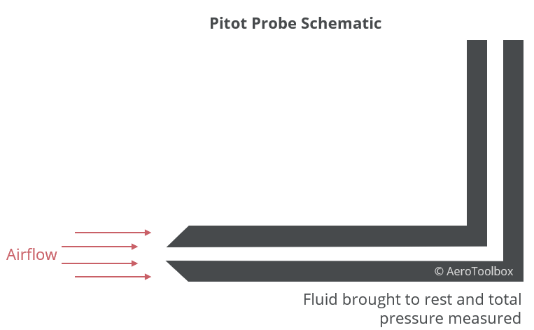
The pitot probe is located in a region of undisturbed airflow and consists of a cylindrical tube open on one side to the airstream. The forward motion of the aircraft forces air into the tube which is then brought to rest by the geometry of the probe. The pressure measured by the pitot tube is known as stagnation pressure or total pressure in accordance with the Bernoulli equation. This measured pressure is the sum of the static and dynamic pressures acting on the aircraft at the location of the probe.
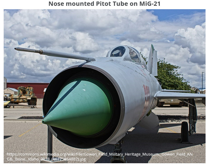
If you consider how a wing generates lift, you should realise that the pressure field around an aircraft is not constant but varies as a function of the geometry of the various surfaces. For example, the air on the upper surface of the wing is accelerated due to the curvature of the wing which causes a drop in the local pressure. It is important therefore to install the pitot probe in an area which is not highly susceptible to local pressure variations. The region under the wing is reasonably undisturbed at lower angles of attack, and so is a common location for the pitot tube. The forward portion of the fuselage or nose are also common locations for the pitot tube but only when there is no propeller and engine mounted in the nose.
Regardless of the pitot tube location, there will always be some error in the pressure reading due to the probe’s position on the aircraft. This position error is corrected for during the design phase of a new aircraft through a flight-test program. The difference in reading between what is read by the probe and what should be read is tabulated and this information made available to the pilot. Any instrument errors are also calibrated out through the flight test program. This explains the difference between indicated airspeed (seen on the airspeed indicator) and calibrated airspeed (determined by test) and is covered in more detail in this handy airspeed conversion tool. The position error in a light aircraft is generally small enough to be negligible as the flying speeds are low.
Static Pressure
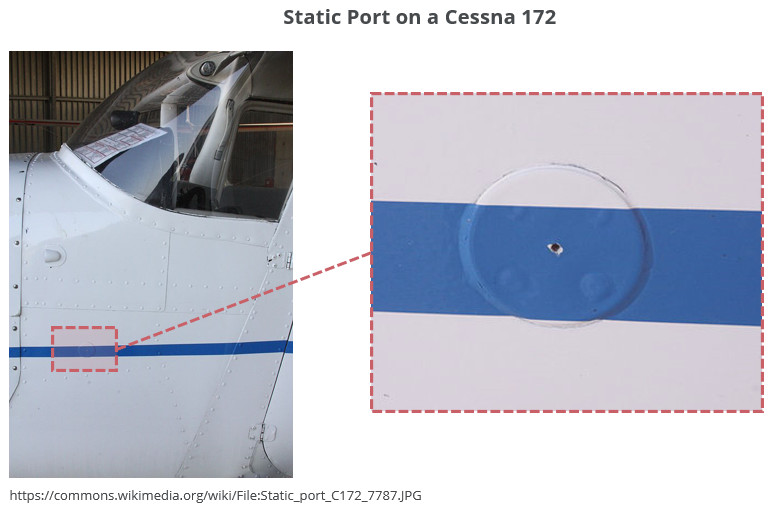
The static pressure is a measure of the ambient atmospheric pressure in which the aircraft is flying. The static pressure is measured through a small vent usually located on the forward fuselage of the aircraft. The vent is nearly flush with the fuselage in order that it sits within the boundary layer and so as not to include any dynamic pressure component. The static port is also subject to position error similar to the pitot tube. The static pressure will vary slightly around the aircraft and so the port must be located where it can provide a good approximation to the ambient atmospheric pressure through all operational angles of attack.
The atmospheric pressure does not remain constant through the atmosphere but varies with altitude at a rate of approximately 1 hPa (hectopascal) for every 30 ft of altitude gained or approximately 0.0295 in Hg for every 30 ft. This relationship between pressure and altitude allows for the aircraft’s altitude to be determined by feeding the static pressure directly to the altimeter. The rate of change of the static pressure is used by the vertical speed indicator to determine the climb rate or descent of the aircraft.
In a bid to improve the reliability of the static pressure reading during manoeuvres, a second static port may be installed on the opposite side of the fuselage to allow for an averaged or balanced reading of the static pressure to be obtained.
It is vital to the safe operation of the aircraft that the instantaneous static pressure be available to the pilot at all times during a flight. A blocked static port will cause the pressure instruments to over or under read depending on whether the aircraft is ascending or descending (this is covered here). An alternate static source is usually available to the pilot in the event that the primary source becomes blocked. This may take the form of an alternate static source selector valve in the cockpit which will open the system up to the ambient cabin pressure. Making use of the cabin ambient pressure as a backup source is only a viable option if the cabin is unpressurized for obvious reasons. The cabin pressure is usually slightly lower than the ambient atmospheric pressure which will result in less accurate instrument readings.
Dynamic Pressure
Dynamic pressure is not directly measured but rather determined as the difference between the total and static pressures that are available through the pitot probe and static port respectively.
Dynamic pressure is used to determine the aircraft’s airspeed based on the mathematical definition of the dynamic pressure, a function of velocity and air density. The velocity can be determined by rearranging the equation as follows:
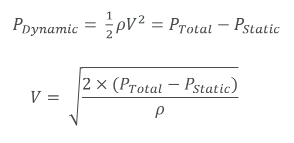
Rearranging the equation, the velocity is a function of both the pressure differential and the air density. The airspeed indicator is calibrated to a sea level density on a standard atmospheric day (mathematical idealization of the atmosphere) which means that the airspeed will over or under read whenever the prevailing atmospheric conditions differ from the sea level standard (majority of the time). The air density decreases with altitude such that the airspeed indicator will under-read as altitude is increased. This is covered in greater detail in the post dedicated to the airspeed indicator (ASI) and it is fundamentally important that a pilot understand the difference between indicated airspeed and true airspeed. Fixing the density to a single atmospheric condition is actually advantageous to a pilot as it means that the aircraft will always stall at the same indicated airspeed regardless of the actual true airspeed.
Pressure Instruments
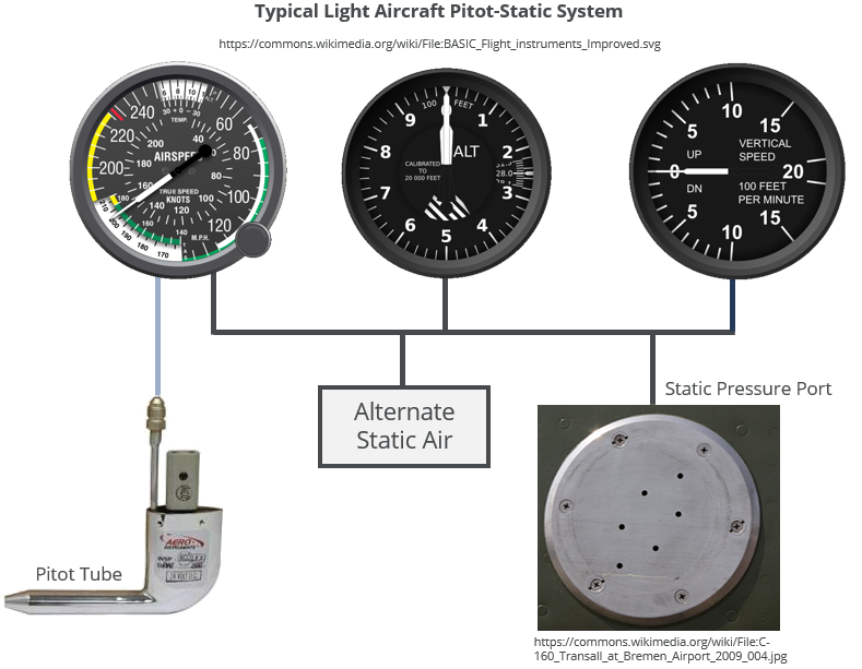
A schematic of the instrument pressure system layout is shown below. The static pressure vent is connected to the airspeed indicator, altimeter, and vertical speed indicator as all three instruments require ambient atmospheric pressure to operate correctly.
The airspeed indicator is also connected to the pitot probe which delivers total (stagnation) pressure to the instrument so that the dynamic pressure can be determined as discussed in the section above.
Further Reading
This post is meant as an introduction to the aircraft’s pitot-static pressure system. Each instrument discussed here is covered in greater detail in the posts linked below.
Airspeed Indicator
Altimeter
Coming soon.
Vertical Speed Indicator
Coming soon.


