This is the third and final post in a three-part mini-series on the aircraft electrical system. In the previous post we discussed the alternator which supplies electricity to the aircraft during engine operation. Now we turn out attention to the battery – specifically the lead-acid battery which is the most commonly installed battery among general aviation aircraft.
Introduction
Lead-acid batteries first appeared in the nineteenth century, yet they remain one of the most prevalent battery technologies in use today: primarily as a starter battery for internal combustion engines. Lead-acid starter batteries make up approximately 20 % of all battery sales; second only to lithium-ion batteries found in cell-phones and laptops.
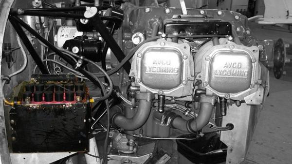
Lead-acid batteries are heavy (they have a low energy-to-weight ratio) and large (low energy-to-volume ratio), but their ability to deliver a high current for a short period of time makes them ideally suited to power an internal combustion starter motor, which requires a short burst of high current to start the engine.
Most light aircraft operate on either a 12 V or 24 V electrical system. The lead-acid batteries that form a part of these systems are built up from cells each outputting 2 V and connected in series to provide the desired voltage. A 12 V battery therefore contains 6 cells, while 24 V requires 12 cells.

Larger turbine aircraft are usually powered by Nickel Cadmium (Ni-Cad) batteries which are more suited to starting turbine engines.
How Does a Lead-Acid Battery Work?
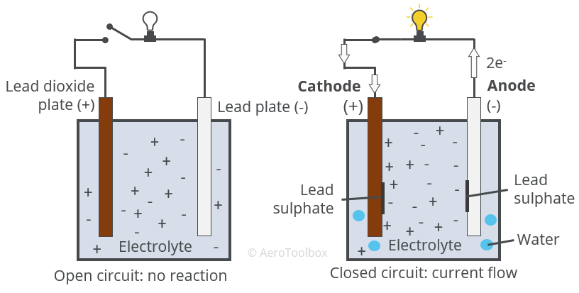
The battery stores chemical energy in the form of a potential difference that exists between two poles of the battery immersed in an electrically conducting liquid solution. Closing a circuit between these two poles causes an electric current to flow between the poles due to the resulting chemical reaction.
Active Materials
The chemical reaction in a lead-acid battery requires active materials for the reaction to proceed. The battery is constructed from two metallic plates, across which a potential difference is formed, immersed in an electrolyte solution which precipitates the reaction.
The active materials found in a lead-acid battery are:
- Lead Dioxide, \( PbO_{2} \), which forms the positive plate.
- Pure lead, \( Pb \), which forms the negative plate.
- Aqueous sulphuric acid, \( H_{2}SO_{4}(aq) \), which forms the electrolyte solution.
An electrolyte is a substance that produces an electrically conducting solution when dissolved in a polar solvent, such as water. Sulphuric acid is mixed with pure or distilled water to form the electrolyte substance. This solution is electrically neutral, but separates into cations (positive charge) and anions (negative charge) which are dispersed throughout the solution.
A battery works because the two metals that are used as the electrodes have a differing affinity for electrons. When the two plates are connected, the lead electrode gives up two electrons which travel through the electric circuit to the lead dioxide electrode. The electrolyte solution is an electrical conductor and closes the circuit. Closing the circuit causes a chemical reaction between the electrodes and the electrolyte. The reaction results in solid lead sulphate \( (PbSO_{4}) \) being deposited on both electrodes, and water being released which dilutes the electrolyte.
The resulting flow of electrons from the negative terminal to the positive terminal is a DC electric current which powers any electrical components connected to the circuit.
Chemical Reaction
Connecting the two electrodes and closing the circuit causes a chemical reaction which results in lead sulphate being deposited onto each electrode/plate and water being released into the electrolyte solution.
The reaction can be broken down into three parts: the reaction at the anode (negative plate), the reaction at the cathode (positive plate), and the overall reaction.
Anode reaction (Lead plate)
The anode is the name given to the plate that receives conventional current during the reaction. Conventional current is defined as current flow from the positive plate to the negative plate.
The pure lead plate forms the anode where the following reaction occurs:
$$ Pb(s) + HSO_{4}^{-}(aq) \rightarrow PbSO_{4}(s) + H^{+}(aq) + 2e^{-} $$
Two electrons are released at the negative plate which flow to the positive plate. Lead sulphate \( (PbSO_{4}) \) is produced, which is deposited onto the lead plate, and hydrogen is released which is reacted to form water at the positive plate.
Cathode reaction (lead dioxide plate)
The following reaction occurs at the lead dioxide \( (PbO_{2}) \) plate:
$$ PbO_{2}(s) + HSO_{4}^{-}(aq) + 3H^{+}(aq) + 2e^{-} \rightarrow PbSO_{4}(s) + 2H_{2}O(l) $$
The two electrons released at the negative plate flow to the positive plate where they combine with the ions in the electrolyte to form a deposit of lead sulphate and water.
Overall Reaction
The overall reaction can be written by combining the reaction at the anode and the cathode.
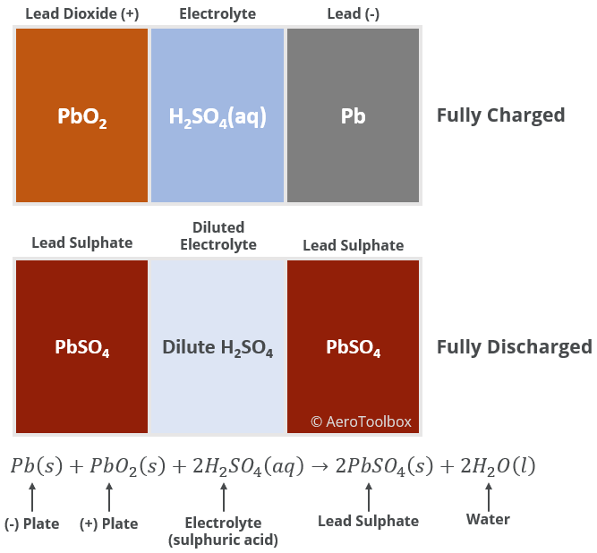
$$ Pb(s) + PbO_{2}(s) + 2H_{2}SO_{4}(aq) \rightarrow 2PbSO_{4}(s)+2H_{2}O(l) \ \left[ EMF = 2.05V \right] $$
Lead sulphate is deposited onto both plates during the reaction and liquid water is produced which dilutes the electrolyte. The reaction outputs an electromotive force equal to 2.05 V.
The changing chemical composition of a lead-acid battery as it discharges is shown below. A fully discharged battery would result in two lead sulphate plates in a solution of highly dilute sulphuric acid.
Specific Gravity and the Electrolyte
We have just described how a discharge of the battery results in the formation of solid lead sulphate and liquid water. It follows then that use of the battery will cause the sulphuric acid in solution to be diluted. The concentration of sulphuric acid in solution therefore provides a convenient manner to assess the state of the battery.
Specific gravity is defined as the ratio of density of any fluid to that of water at 4°C. Water has a density of 1.0 kg/L (1.0000 kg/L @ 4°C and 0.9982 kg/L @ 20°C) at room temperature which provides a convenient means to compare the relative densities of different fluids.
We have previously discussed how oil and fuel have specific densities less than one. In a mixture of fuel and water the denser water will settle below the fuel, providing an easy method to detect fuel contamination.
An electrolyte of sulphuric acid and water is more dense than pure water due to the presence of the sulphur in the solution. As the electrolyte is diluted by the action of the battery, the concentration of sulphur in solution will decrease and the concentration of water in the solution will increase. This leads to a decrease in the specific gravity of the electrolyte as the battery discharges.
A hydrometer is an instrument used to measure relative density or specific gravity of liquids, and so provides a means to measure the condition of the lead-acid battery. A sample of the battery fluid can be tested, and the specific gravity determined. When this drops below a pre-determined value the battery should be replaced.
Construction and Design of a Lead-Acid Battery
We have described in detail the chemical reaction between two plates that underlies the lead-acid battery. Now we discuss how this is implemented in the design and construction of a practical battery.
Composition of a Battery Cell
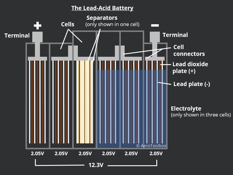
The chemical reaction that occurs in a lead-acid battery cell produces an EMF of just over 2 V. The output of the battery is obtained by connecting these 2V cells in series until the desired voltage is met. A 12 V battery therefore requires six cells, and a 24 V battery twelve cells. Each cell is isolated by a non-conducting battery case made of rubber or a hard plastic.
Each cell contains multiple lead (-) and lead dioxide (+) plates between which the chemical reaction takes place. The cell is constructed such that a single lead dioxide plate sits between two lead plates. You can differentiate between the plates based on their color. The lead plate is a grey color and the lead oxide plate a chocolate brown.
It is necessary that the plates do not contact each-other as this would short-circuit the battery. The plates are kept apart by separators, made from a porous non-conducting material like rubber, fiberglass or resin-infused paper. This allows the electrolyte to move freely between the plates.
In traditional lead-acid batteries the plates are immersed in liquid electrolyte. This is termed a flooded lead-acid battery as the electrolyte is free to move about in the cells. Charging the battery converts the lead sulphate that is deposited during discharge back into sulphuric acid. This reaction consumes water, and so a periodic topping up of the water levels in the cells of a flooded battery is required to maintain the condition of the battery. Distilled water should always be used when performing battery maintenance.
Newer lead-acid batteries are sealed and do not require any maintenance. Sealed battery designs do away with the full immersion of plates in liquid electrolyte. Two common sealed battery designs are the gelled electrolyte type and an absorbed glass mat design.
In absorbed glass mat (AGM) batteries, the plate separators are replaced by a glass fibre mat which is soaked in electrolyte. There is sufficient electrolyte in the mat to keep it wet and to facilitate the chemical reaction, but not so much that the electrolyte will spill out if the battery is punctured. The design of the mat is such that the hydrogen and oxygen gas generated during charging is easily able to pass through the separator, where it will oxidize on the opposing plate. This is not possible in a flooded battery where bubbles of gas float to the surface of the fluid where they are lost to the atmosphere.
A gel sealed battery mixes a silica gelling agent to the electrolyte, converting the electrolyte into a gel-like paste. The gel provides many of the same advantages seen in the AGM design.
AGM and gel batteries can both be installed in any orientation and do not require any maintenance. Both battery types use a one-way blow-off valve to prevent over pressurization of the battery during charging. These batteries are often called “valve-regulated lead-acid”, or VRLA designs.
Design for Energy or Power
Batteries either designed to operate at a high energy density or a high power density. A high energy density battery is able to store large quantities of energy and release that energy slowly and reliably over a long period of time. These are termed deep cycle batteries and are designed to be regularly discharged between charges, and operate over many cycles.
Batteries with a high power density are designed to release a large amount of energy in a short period. These batteries are ideal for starting an aircraft or car engine where a very high current is required at the starter motor for a short period to turn the engine over. These batteries are called SLI batteries (starting, lighting, and ignition) and are designed to be installed alongside an alternator or generator that will continuously charge the battery while the engine is operating.
Batteries in Series and Parallel
Individual cells in a battery are connected in series in order reach the desired voltage. The EMF of a single lead-acid battery cell is 2.05 V such that six cells are required to make a 12 V battery.
Each cell contains several positive and negative plates which are connected in parallel such that the voltage in the cell remains constant at 2 V, but the capacity of the battery increases.
Battery capacity is typically measured in Ampere-hours (Ah). A 1 Ah battery will supply one Ampere of current for one hour at the battery’s nominal rated voltage.
- Connecting battery cells in series will increase the overall voltage output while keeping the battery capacity constant.
- Connecting battery cells in parallel will keep the voltage constant but increase the capacity by the sum of the individual battery capacities.
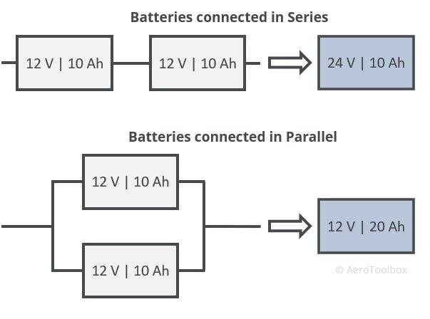
Connecting batteries in parallel allows the combined battery to be run for longer before fully discharging.
Charging a Battery
Charging a battery involves reversing the chemical reaction that occurs when the battery discharges. The lead sulphate formed on the battery plates during discharge is converted back into sulphuric acid, and the water in the electrolyte is decomposed into oxygen and hydrogen gas.
In order to charge a battery, a voltage must be applied to the cells that is higher than the output voltage of the battery. This higher voltage is then able to overcome the battery’s own EMF output (counter-electromotive-force), reversing the reaction through a process of electrolysis. Electrolysis is the decomposition of water into oxygen and hydrogen gas under the influence of an electric current.
The aircraft’s alternator is responsible for charging the battery. The alternator output must always be greater than the battery’s output to ensure that the battery can be fully charged. This is why aircraft alternators usually output approximately 14 V in a 12 V battery system and 28 V in a 24 V battery system.
Holding the alternator voltage constant automatically regulates the charging rate of the battery. The battery will charge faster when the battery voltage is lower, and slow as the battery reaches full charge, when the difference between the generator voltage and battery voltage reduces.
The hydrogen and oxygen gas that is formed during electrolysis is highly flammable and so care must be taken to avoid sparks in the vicinity of the battery during charging. Modern VLRA batteries are better at facilitating the oxidation of the gases formed through improved separator design and are also fitted with a valve to vent any excess gas that is formed. Never-the-less, care must be taken when working in the vicinity of a charging battery to avoid a fire.
Charging a battery is an exothermic reaction – heat is given off during the chemical electrolysis. If the rate at which heat in the battery is generated exceeds the ability of the battery to expel that heat, then the battery temperature will continue to rise, and if not controlled, the battery could experience a thermal runaway and destroy itself. This is a dangerous situation where the internal temperature in the battery becomes so great that it boils the electrolyte and melts the plates and battery casing. In an extreme thermal runaway event, the battery could cause an electrical fire or even explode.
Thermal runaway is negated by regulating the charging voltage and monitoring the resulting temperature. A higher voltage differential between the battery and the charger will result in increased current flow into the battery, raising the battery temperature. As the temperature rises, the internal resistance in the battery drops, which only serves to increase the current flow, accelerating the runaway. If a thermal runaway is suspected, then the battery should be immediately isolated and properly disposed of once the runaway has been contained.
This brings us to the end of this tutorial and the end of our mini-series on the aircraft electrical system. If you enjoyed this post or found it useful as a study aid then please introduce your colleagues and friends to AeroToolbox.com and share this on your favorite social media platform. Thanks again for reading.


