Internal combustion engines must be adequately lubricated and cooled while running in order to provide safe operation and to function as the manufacturer intended. In this post we focus on the lubrication and cooling systems of a typical internal combustion aircraft engine.
Lubrication System
Internal combustion (IC) engines are made up of many high-speed, rotational components operating at high temperature. A typical general aviation IC engine operates at approximately 2000 rpm and is expected to operate for 2000 hours between major overhauls. Proper lubrication of all moving and rotating parts is vital in order to achieve this. Lubrication is provided by aviation grade oil, which is pumped continuously through the engine during operation.
Before we delve into the details of the oil system let’s start with a general overview of the properties of oil.
Properties of oil as a lubricant
Oil performs a number of primary functions as it is circulated around an engine.
- It reduces the friction between moving parts, protecting the engine components.
- Provides a gas seal between the piston and cylinder walls.
- Aids in cooling the engine by removing heat from the engine.
- Removes foreign particles and contaminants through a filtering process.
The oil also provides a damping force to parts of the engine which are subjected to shock loadings, for example, a piston moving in a cylinder subjected to detonation.
It is very important that the correct oil is used in an aircraft engine. The engine manufacturer will specify a list of approved aviation oils to be used, which is dependent on the prevailing climate in which the aircraft operates.
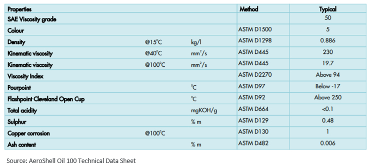
The table below is extracted from the datasheet of a common aviation lubricating oil, Aeroshell Oil W100. You can download the datasheet here. We’ll use this reference as a guide to examine the various properties that make a good aviation oil.
Viscosity
Viscosity is defined as a measure of a fluid’s resistance to deformation and is a function of the internal frictional forces between layers of the fluid (shear stresses). In simpler terms one can think of viscosity as a measure of the thickness or stickiness of a fluid. For example: syrup is much thicker and pours much more slowly than water, and as such we say that syrup is a more viscous fluid than water (syrup has a higher viscosity than water).
Oils are standardized and defined by their viscosity grades. This standardization was completed by the Society of Automotive Engineers (SAE) in order to provide regulatory oversight, and you will see many oils referred to by the SAE grading. In the Aeroshell W100 example shown above, the SAE grading of the oil is 50. This is an oil designed for to be used when the aircraft is operated in a temperate climate (15°C – 30°C).
Temperature has a large effect on the viscosity of the oil. Cooler temperatures result in the viscosity increasing (more difficult to pour) and warmer temperatures cause the viscosity to drop (easier to pour). It is for this reason that different grade oils are preferred for operating in different climates. In colder climates an oil of lower viscosity is preferred as this will ensure that the oil isn’t so thick as to make starting the engine difficult on a cold day. Similarly, using an oil with too low a viscosity in a hot climate could result in the viscosity dropping dangerously low when the engine is operating at a high temperature; and the oil could fail to provide the lubrication necessary.
Aircraft engine oils are typically designated by a slightly different grading to the SAE ratings discussed above, but the two are equivalent and you can convert between them as follows.
| SAE Grade | Aviation Grade |
|---|---|
| SAE 30 | 65 |
| SAE 40 | 80 |
| SAE 50 | 100 |
| SAE 60 | 120 |
Kinematic Viscosity
The table from the specification sheet provides values of kinematic viscosity for the Aeroshell W100 oil at 40°C and 100°C. This provides us with a convenient way to analyse the effect that temperature has on the viscosity of the oil.
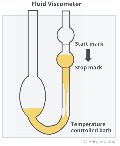
Kinematic viscosity is simply the viscosity of the fluid divided by the fluid density and can be thought of as a measure of the oil’s internal resistance to flow under the action of gravity alone. The kinematic viscosity of the oil is determined through test by measuring the time taken for a known volume of oil to flow a fixed distance through a specially calibrated tube. The kinematic viscosity of the oil is highly temperature dependent and so the test must be performed under laboratory conditions where the temperature can be closely monitored.
It is standard to write the kinematic viscosity in units of centistroke (cSt or mm²/s). Referring to the specification sheet for Aeroshell W100 the kinematic viscosity for this oil is given as 230 cSt at 40°C and 19.7 cSt at 100°C. This oil is 11.7 times more viscous at 40°C than at 100°C. This provides some insight as to why it is so important to select the correct oil to match the prevailing ambient conditions.
Density and Specific Gravity
Density is a measure of the mass of the substance per unit volume. If the oil density and the volume that the engine requires is known, then the total mass of the oil can be easily determined by multiplying the density and the volume.
The density of the Aeroshell W100 oil is stated as 0.886 kg/L. The density of water is 1.0 kg/L (1.0000 kg/L @ 4°C and 0.9982 kg/L @ 20°C) and so immediately we can see that oil is less dense than water. This means that if you fill a beaker with oil and then add water to the solution, the water will always sink to the bottom of the beaker as water is more dense (heavier per unit volume). This is very advantageous to pilots as any impurities in the oil system will always sink to the bottom of an oil sump (container where oil is housed in an aircraft) where it can be easily removed. Fuel is also less dense than water which is why as part of your pre-flight you always extract a small amount of fuel from the base of the fuel tank to check for contamination.
The ratio of the density of any fluid to that of water at 4°C is known as the specific gravity of the fluid. In this instance the specific gravity (SG) of the oil is 0.886. Another term for specific gravity is relative density. These can be used interchangeably.
Pour point
The pour point is the lowest temperature at which a fluid will pour. The pour point of Aeroshell W100 is stated as -17°C. It is important to ensure that the coldest anticipated ambient temperature that the aircraft will be operated at is well above this temperature.
Flash point
This is the lowest temperature that the oil can be heated to before it releases vapors, that when mixed with air and exposed to an ignition source, will ignite but not continue to burn. The flash point of Aeroshell W100 is 250°C.
Fire point
This is the temperature above which there are sufficient vapors released by the oil that the oil will continue to burn if exposed to an ignition source.
Ash Content
Aeroshell W100 is an ashless dispersant oil which means that certain additives have been added to the oil to aid in the removal of contaminants that may otherwise clog or plug oil passageways. These contaminants (usually by-products of combustion) remain suspended in the oil until they are deposited in the oil filter as the oil circulates through the engine, or are drained away when the oil is changed. This prolongs the engine life and reduces engine wear.
Engine Lubrication Systems
Aircraft engines generally employ one of two lubrication systems: a wet sump or a dry sump system. The primary difference between the two systems is where in the system the oil is stored.
In both cases oil from a reservoir (sump) is pumped under pressure to the engine, where it lubricates the bearings and mechanical components, before returning back to the reservoir.
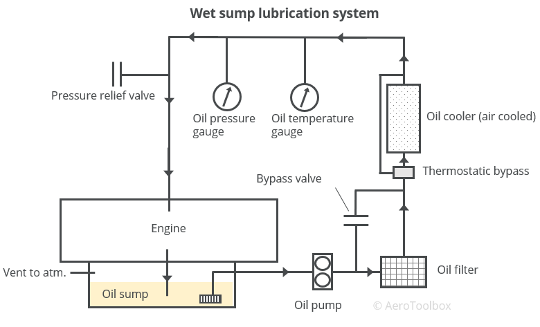
Wet Sump
In a wet sump system, the crankcase of the engine works as a built-in reservoir (sump) for the oil in the lubrication system. Since the crankcase makes up the lowest part of the engine block, the oil that is pumped to the bearings naturally returns to the sump under the action of gravity.
The oil is pumped under pressure by a mechanical fuel pump which is driven off the accessory shaft of the engine. The oil passes through a filter to remove any contaminants, through an oil cooler to regulate the temperature of the oil, and finally into the engine. Once the oil enters the engine it flows through a number of passageways in the engine, lubricating the internal components before draining back into the sump in the crankcase.
A bypass valve is positioned between the mechanical pump and the filter to protect the system in the event that the filter becomes blocked. If this happens, the pressure build-up will cause a mechanical valve to open, allowing the oil clear passage to the engine. Unfiltered oil is clearly preferable to no oil at all, as oil starvation will result in the engine seizing.
In an air-cooled engine the oil system is responsible for approximately 30 % to 40 % of the total cooling. The oil attracts a lot of heat as it passes through the engine which is dissipated through an air-cooled oil-cooler before re-entering the engine. The oil cooler extracts heat from the oil, lowering its temperature, thereby lowering the overall temperature of the engine. A thermostatic bypass provides a means of temperature regulation for the oil. If the oil is too cool (viscosity increases at cooler temperatures), then the bypass will open, diverting the oil away from the cooler and back into the engine.
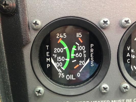
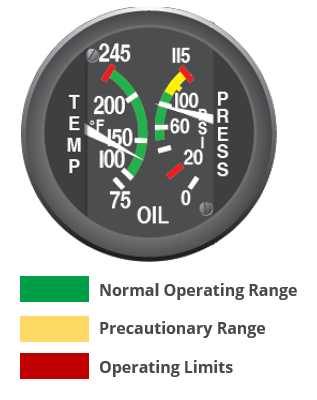
Oil temperature and pressure gauges in the cockpit allow the pilot to monitor the oil system. The location of the sensors determines what information the pilot is able to gather from the gauges. In most cases both sensors are located after the oil cooler but before the oil enters the engine. This way the pilot is assured that the oil that is entering the engine is within the correct temperature and pressure range. A pressure drop or a temperature increase would indicate that the pump is malfunctioning or that the cooler is not working as expected.
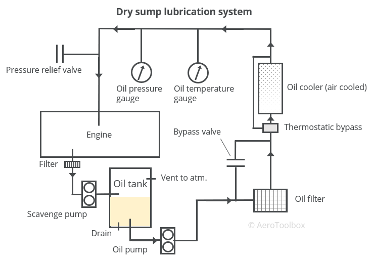
Dry Sump
A dry sump system contains many of the same components described in the wet sump system, with the primary difference being that the oil is stored in an external oil tank away from the engine. Since the oil tank is separate from the engine a second oil pump, called a scavenge pump, is required to pump the oil from the engine back to the tank. The oil leaving the crankcase usually passes through a filter before being pumped back to the dry sump reservoir.
The external oil reservoir is commonly placed above the engine to make use of gravity to assist in feeding oil to the engine.
A dry sump has several advantages over the wet sump system. These include:
- By storing the oil in a separate reservoir and providing scavenge pumps to return the oil to the sump, there is little risk of the engine experiences oil starvation under high-g manoeuvres or when flying inverted. It is for this reason that aerobatic aircraft make use of a dry sump system.
- It is easier to control the oil pressure and temperature in a dry sump configuration as the oil is stored away from the hot engine. As a result, the oil temperatures are usually cooler in a dry sump design.
A dry sump arrangement does add cost, complexity, and weight to the oil system as the reservoir is no longer integral to the engine and additional pumps are required to scavenge the oil back to the tank.
System Malfunctions
A pilot can monitor the oil pressure and temperature from within the cockpit. The sensors for these gauges are usually located just before the oil enters the engine, which provides a clear indication as to the state of the oil being used for lubrication.
It is important that a close eye is kept on the temperature and pressure of the oil at all times during a flight. A deviation of either could be a warning of an impending engine failure.
Some common faults and suggestions on a course of action to rectify pressure and temperature anomalies are given below.
Oil Pressure Anomalies
Oil pressures outside of the normal operating range, both excessively high or low, can be dangerous, and if encountered the pilot should always attempt to land as quickly as safely possible.
High oil pressures could indicate that a system blockage or faulty pressure relief valve is causing the system pressure to increase beyond a safe level. If the pressure continues to build, then there is potential that the entire system could fail as the increased pressure ruptures the system at the weakest point.
Low oil pressure can be an indication of a fault in the oil pump, a leak in the system, or a low total oil level due to excessive oil consumption of the engine. As aircraft engines age and piston rings start to wear, the engine may start to burn oil that escapes in the gap between the piston and cylinder wall. It is important as part of a pre-flight inspection to always check that sufficient oil is present in the system. Whenever oil is added to the engine it should be recorded in the aircraft flight folio. This way any excessive consumption should be identifiable if the consumption trend is monitored.
A fluctuating oil pressure is often a warning sign that a problem is beginning to manifest itself. If the oil pressure begins to fluctuate during flight, then it is prudent to have a mechanic look over the entire system.
Oil Temperature Anomalies
It is important to monitor the temperature of the oil at all stages during a flight as a rising oil temperature indicates that the engine is receiving insufficient cooling. In some situations, especially on a particularly hot day, the pitch attitude of the aircraft while it is climbing may result in an oil temperature rise due to insufficient engine cooling. Most light aircraft are air-cooled and as the pitch attitude is increased, it is more difficult for the engine to receive the volume of air necessary to ensure adequate cooling. This will manifest as an increase in the cylinder head temperature as well as the oil temperature. The best solution to mitigate this is to reduce the climb angle and climb at an increased speed. This will provide greater airflow into the engine, resulting in a drop in cylinder head temperature. Another option is to perform a step-climb, leveling off periodically to cool the engine until the desired flight level is reached.
The oil temperature should not be viewed in isolation but monitored in conjunction with the oil pressure. In all cases any abnormal reading should be treated as serious and the best course of action is usually to land as soon as safely possible.
Cooling System
In an ideal world all the chemical energy stored in fuel would be converted directly to usable engine thrust during the combustion process. If this were the case, then we could say that the engine is 100 % efficient. Unfortunately, we live in the real world, where much of the energy stored in the fuel is used to overcome engine friction or converted to heat and noise as a by-produce of combustion.
In fact, a typical internal combustion engine is only 25% – 35% efficient meaning that 65% – 75% of the total energy released by combustion of the fuel is used to run the engine or dissipated as heat.
The pie chart below shows a typical breakdown of how the energy released during combustion is “spent” to produce useful thrust to propel the aircraft forward.
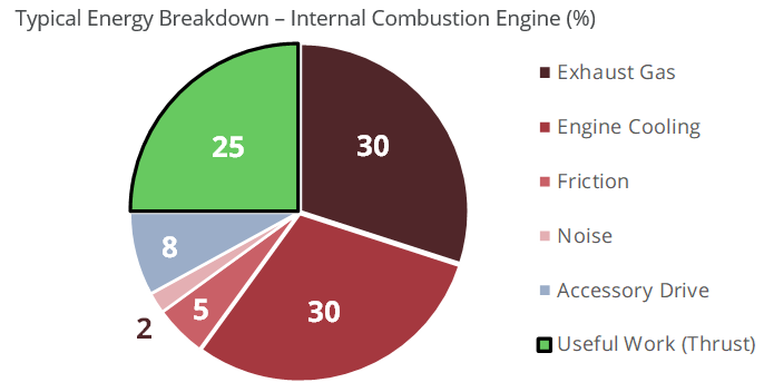
With somewhere in the region of 60% of the total energy being converted to heat, it quickly becomes apparent that an efficient method to dissipate the heat is required in order for the engine to continue to safely operate.
Why is Cooling Necessary?
If there was no external cooling of the engine, the temperatures in the cylinders would rise to dangerous levels, detonation of the air-fuel mixture would begin, and ultimately the engine would get so hot that catastrophic failure would occur.
Most light aircraft make use of air cooling and oil cooling to keep the engine temperatures under control. Some aircraft engines, notably the Rotax engines, use liquid cooling (through a radiator) as the primary means to cool the engine.
Oil Cooling
We have already covered oil cooling in this post, but to recap: the oil is an effective means to transfer heat out of the internal components of the engine and to dissipate the heat to the atmosphere through the oil cooler which forms a part of the oil system.
Air Cooling
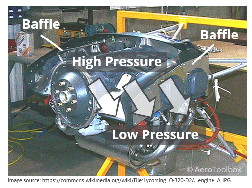
Air cooling plays a vital role in maintaining the temperature of the cylinders at a safe level. Air cooling works by providing a continuous passage of ambient air in through the front of the cowling and out through the rear of the engine compartment. This air is carefully ducted to each cylinder head, and other hot parts of the engine, through the use of baffles. The cool ambient air passes over cooling fins on each cylinder head, absorbing the heat, and transporting it out and away from the engine.
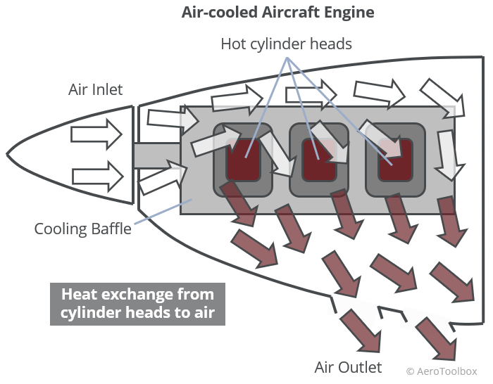
Engine Baffles
Engine baffles control the flow of air in the engine compartment through the use of aluminium guides and rubber seals. The aim of a baffle is to create a region of high pressure above the engine cylinders. The lower portion of the engine compartment forms a low-pressure region due to the outflow openings at the base of the cowling. This pressure difference induces a suction of air from the high-pressure region to the low-pressure region. This suction down past the cylinder heads provides an efficient means to air-cool the engine.
Cowl Flaps
There are certain phases of flight where additional air cooling may be required in order to keep the cylinder head temperatures down. A sustained climb on a hot day, or even a long taxi and hold are both cases where the forward airspeed is low (or zero), which makes air cooling less effective.
Cowl flaps are hinged flaps located on the underside of the engine cowling (in the low-pressure region described above) which can be opened and controlled from the cockpit when additional cooling is required. Opening the cowl flaps results in increased airflow through the engine compartment which assists in cooling the engine.
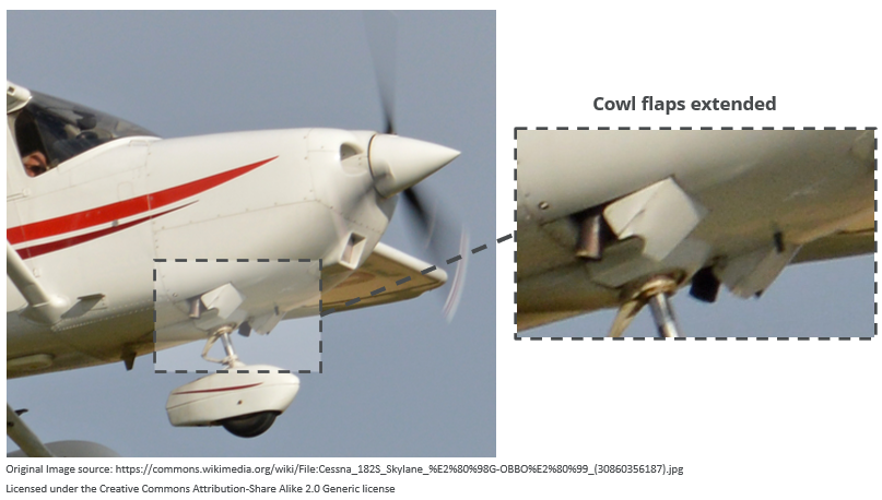
Cowl flaps can be quite large and always protrude into the airstream when extended. This results in an increase in drag which would result in increased fuel consumption or a reduction in cruise speed when left open. It is for this reason that the cowl flaps are retracted when not required, usually at the top of the climb. Leaving the cowl flaps open during a descent is undesirable and could result in shock-cooling of the cylinder heads which should be avoided.
This brings us to the end of this post on the lubrication and cooling systems present on an internal combustion aircraft engine. Next up we discuss the fuel system. Thanks for reading and please remember to please share this if you found it helpful.


