An aircraft hydraulic system allows for forces to be applied, multiplied, and transmitted from one location to another through an incompressible fluid medium. Hydraulics are a critical system on almost all modern aircraft. Light aircraft primarily make use of hydraulics to augment and transmit braking forces from the cockpit to the brake disk or drum. Larger, more complex aircraft may use hydraulics to actuate landing gear, flaps and control surfaces in addition to braking and nose-wheel steering.
Principles of Hydraulic Operation
A hydraulic system operates on the principles of Pascal’s Law and the conservation of energy to transmit a force and displacement from one point to another in the system. The basic operating principles of a hydraulic system are described below.
Pascal’s Law
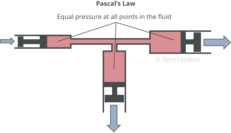
Pascal’s Law states that the change in pressure at any point in a contained incompressible fluid must be transmitted throughout the fluid such that the pressure change occurs equally everywhere.
This means that if the pressure inside a hydraulic line is changed, e.g. the pilot depresses a brake pedal, the increased pressure due to the reduced volume in the system will be transmitted equally to all points in that system.
Force Multiplier
Pressure is defined as the force per unit area:
$$ Pressure = \frac{Force}{Area} $$
which is easily rearranged in terms of the force:
$$ Force = Pressure \times Area $$
Pascal’s Law states that any pressure change in the system will be the same everywhere in the fluid. This means that the input and output force in the hydraulic system are related to each-other by the ratio of their respective cylinder areas.
$$ F_{2} = F_{1}\frac{A_{2}}{A_{1}} $$
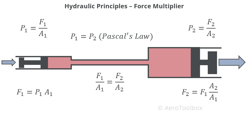
If the area of the output cylinder is twice that of the input cylinder, then the force output will be twice the input force. Hydraulic lines therefore have the property of being a force multiplier; this is how a small jack is able to lift a large vehicle.
Conservation of Energy
The principle of the conservation of energy applied to a hydraulic cylinder dictates that the system cannot do more work than is done on it. The input and output work must therefore be equal for the conservation law to apply.
Mechanical work is defined as the force applied multiplied by the displacement through which the object moves as a result of that force.
$$ Work = Force \times Displacement $$
We can therefore derive a formula that describes the displacement of the output cylinder in terms of the input cylinder.
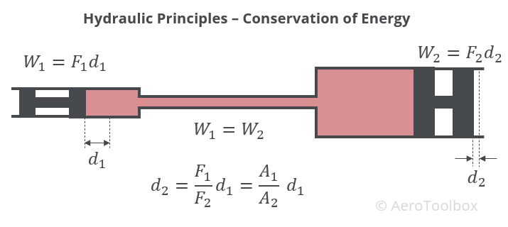
In cases where the output cylinder area is larger than the input cylinder, the displacement at the output will be smaller by the ratio of input to output area.
Fluid Properties
Hydraulic systems work on the principle that fluid, unlike air, is virtually incompressible. This makes it a good medium to transmit and multiply forces. Incompressibility is not the only requirement for a useful hydraulic fluid; viscosity, stability, and the tendency to resist vaporization are important too.
Viscosity
Viscosity is defined as the internal resistance to flow and is a property that has been discussed in previous posts in relation to fuel, oil, and water. A fluid with a high viscosity such as honey flows slowly while oil which has a low viscosity pours easily. The viscosity of a fluid is not constant but varies with temperature. Lower temperatures increase viscosity, creating more resistance to flow. Higher temperatures have the opposite effect, lowing the viscosity and increasing the ease at which the fluid will flow.
A hydraulic fluid must have sufficient viscosity such that it aids in the lubrication and protection of the entire system, but not so great that it offers resistance to flow during operation. A typical hydraulic system is made up of cylinders, pistons, valves and pumps. If the viscosity drops too low then these components will not adequately seal, resulting in leaks in the system and poor performance.
The viscosity must also be considered through the full range of the aircraft’s operating temperature envelope to ensure that the system performs as intended; both in the cold and in hot and humid conditions. It is worth pointing out that the temperature of the fluid may not be constant throughout the systems as local hot-spots can occur when fluid is forced through a small orifice or through a set of gears or bearings.
Fire and Flash Point
The fire and flash points fluid properties that describe the fluid’s ability to resist high temperatures and combustion. The flash point is the temperature at which sufficient vapor is released by the fluid to momentarily combust if an ignition source (spark) is applied.
The fire point occurs at a higher temperature and is that temperature at which sufficient vapor is present to sustain combustion if exposed to a spark or flame.
A good hydraulic fluid has a high fire and flash point and will not release much vapor through the usual operating temperature range.
Chemical Stability
Chemical stability refers to the fluid’s ability to resist oxidation and deterioration during a typical operational lifespan. It is important that the fluid is able to operate as designed during periods of high temperature where deterioration of the fluid is accelerated.
The fluid must also resist chemical breakdown if exposed to air, water and other contaminants which are most prevalent when the aircraft is operating in hot and humid climates.
Types of Hydraulic Fluids
Described below are a few fluids commonly used in an aircraft hydraulic system.
Mineral Based Fluids
These fluids are petroleum based and are dyed red for easy identification. Mineral based fluids are commonly used on light aircraft and must be used in conjunction with synthetic rubber hoses and seals to avoid leaks and corrosion.
Polyalphaolefins
This is a fire-resistant fluid which may be used in place of a mineral based fluid if care is taken to limit its use when temperatures are low. The viscosity of these fluids increase significantly at low temperatures compared to mineral based fluids. Always refer to your Pilot’s Operating Handbook for a list of approved fluids to be used in your aircraft.
Phosphate Esters
Phosphate esters are predominantly used in larger transport category aircraft and were developed after World War Two as a response to the increase in the number of hydraulic brake fires resulting from the higher landing speeds of more modern aircraft. These fluids are colored purple and have very good fire-resistant properties.
Design of an Aircraft Hydraulic System
Schematic Design
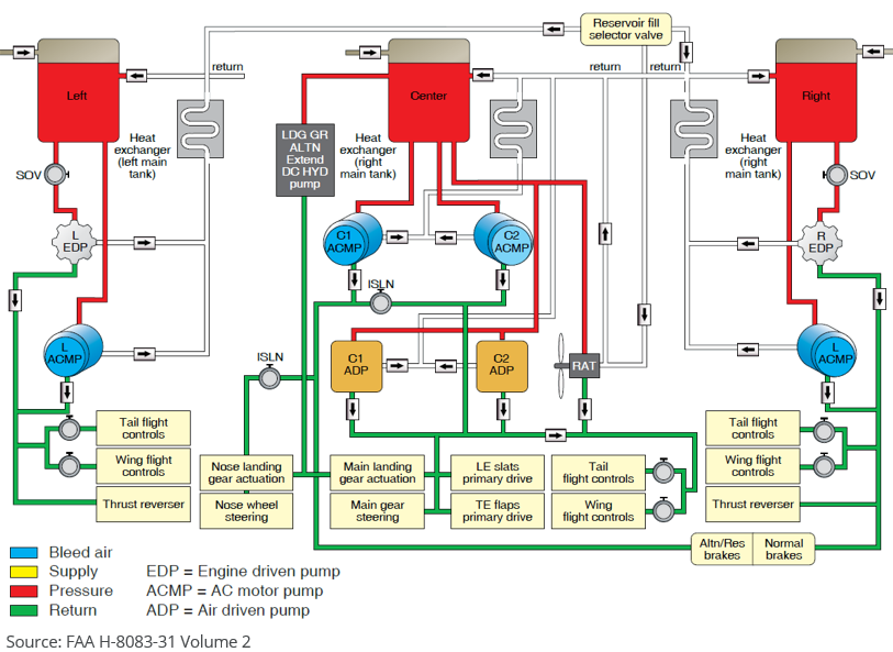
An aircraft hydraulic system can range from very simple: an unassisted brake system on a light aircraft, to very complex. The hydraulic system on a commercial jet airliner is designed with multiple pumps, reservoirs and fluid passages, and typically drives the flight control system, brakes, high-lift devices, spoilers and nose-wheel steering.
Regardless of the complexity, all hydraulic systems comprise of a reservoir to store fluid, a pump (could be a piston actuated by a foot force) to drive the system, valves to control the direction, speed and pressure of fluid flow, a filter to remove impurities, and an actuator to apply a force on the output.
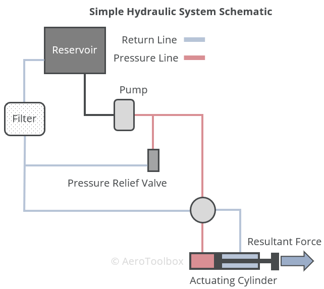
When the hydraulic system is activated, the pump pushes fluid under pressure to the high-pressure side of the actuating cylinder. This forces the piston in the cylinder to move in the direction of the applied pressure gradient. The fluid on the low-pressure side of the cylinder is forced out and returns to the reservoir via a filter to remove any impurities. Depending on the type of actuator, the applied pressure may be reversed to move the actuator in both directions.
Open Center Systems
Hydraulic systems are classified as either open-center or closed-center. In open center systems the various actuators are arranged in series such that fluid passes through each selector valve before returning to the reservoir. The fluid passes freely through each selector valve unless the valve is positioned to operate the actuator, in which case the actuator is moved as pressure builds up on the pressure side of the piston. The design of an open center system is such that the system is only under pressure while an actuator is operating. With all actuators idle the pump is free to circulate the fluid through the system.
Closed Center Systems
A closed center system places the actuators in parallel to one another. This requires that the pump output be controlled to accommodate a differing number of actuators operating simultaneously. The arrangement is such that the system is always under pressure which results in a quicker response when an actuator is activated.
Hydraulic System Components
A typical hydraulic system comprises a number of components which work together to deliver a predictable and repeatable force response at the output actuating cylinder.
Reservoirs
A reservoir works as a storage space in the system for hydraulic fluid. It is important that sufficient fluid is present in the system to provide an adequate supply in all operating conditions. The fluid flows from the reservoir into the system where it performs the required actuations before returning to the reservoir. Temperature changes can result in the fluid volume changing and so the reservoir is designed to act as an overflow during hot operation. Excess fluid is stored in the reservoir to mitigate leaks in the system which would otherwise cause the system to stop operating once a critical fluid level was reached.
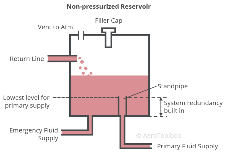
Non-pressurized reservoirs are vented to the atmosphere to allow any air trapped in the system to vent. As the level in the reservoir drops, air enters through the vent to prevent a vacuum from forming. Pressurized reservoirs may be necessary if the aircraft operates at very high altitudes where a positive pressure in the reservoir ensures that the fluid flows into the pump at high altitudes where the ambient pressure is low.
It is important to reduce swirling and surging of the hydraulic fluid in the reservoir as far as possible. Baffles and fins are usually incorporated to reduce the motion of the fluid during flight, and to keep the formation of bubbles to a minimum.
Redundancy should always be built into the hydraulic system to ensure that failure of a single component does not result in failure of the whole system. The primary hydraulic pump is a critical component and as such there is usually an emergency pump installed downstream of the reservoir to operate if the main pump fails. The emergency pump is usually electric powered and runs off the aircraft’s electrical system.
A common reservoir design provides two outlets from a single reservoir. The main pump is fed via a standpipe which sits above the reservoir floor. If the level in the reservoir drops below the level of the standpipe, the emergency feed is activated which is fed from the reservoir floor. The fluid level may slowly drop due to an undetected leak which would result in a full system failure if both pumps were fed from the same level. Feeding the main pump from a point above the floor also ensures that contaminants don’t get pumped through the system as these heavier impediments should sink to the floor under the action of gravity.
An inline reservoir is a standalone unit which is connected in series to the system. Some systems make use of an integral reservoir where excess fluid is stored in a space set aside in a large component which forms a part of the system. A large brake drum may for example act as a reservoir in a smaller hydraulic system.
Filters
A filter is necessary in a hydraulic system to remove any foreign particles or contaminating substances from the system. During normal operation, wear and tear of the valves, pumps and other components cause tiny particles of metal to break off and go into suspension in the fluid. These particles must be removed by the filter to prolong the life of the various components and to avoid abrasion.
Filters can be fitted in low pressure regions of the system (return line), in the reservoir itself, or on the pressure line. The make-up of the filter will differ depending on where it is installed.
Most hydraulic systems are fitted with a filter bypass valve. This will open under pressure if the filter becomes blocked which ensures that the fluid cycle is completed, and the system continues to operate.
Pumps
A hydraulic system requires a pump to power the system and ensure that fluid under pressure is delivered to the actuators when required. In the simplest hydraulic systems, the pump is provided by a piston and cylinder arrangement that increases the fluid pressure when pressed. This is how many light aircraft braking systems operate.
Larger aircraft make use of a primary engine-driven hydraulic pump alongside an auxiliary electric pump in the event that the primary pump fails. Typically the hydraulic systems in these aircraft drive not only the braking system but also flaps and landing gear retraction systems.
Some aircraft are also supplied with a hand-operated pump which can be used in an emergency, or when the aircraft is on the ground and the engine is not operating.
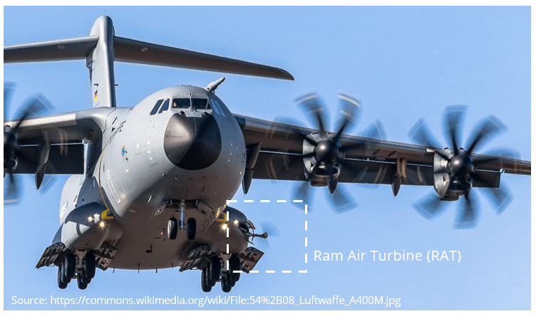
An aircraft may also be fitted with a Ram Air Turbine (RAT) which is a small wind turbine that is deployed into the freestream in the event of a pump failure. The turbine can then be used to power a backup hydraulic pump in an emergency such as an engine failure which would otherwise cause the system to lose hydraulic pressure.
Pumps can be classified as either positive displacement or non-positive displacement. A positive displacement pump is the most common type used in hydraulic applications and works by trapping a fixed amount of fluid at the pump inlet and forcing (displacing) that trapped volume into the discharge pipe at the outlet.
Positive (Fixed) Displacement
A common positive displacement pump found in aircraft hydraulic systems is the gear pump. These pumps consist of two counter-rotating gears which are meshed to create a pressure through the transport of a fixed volume of fluid per revolution. The pump takes fluid from the suction or input side and transports it to the discharge or output side of the pump.
One of the gears is driven by the aircraft engine via an accessory drive. The other gear is free to rotate and is driven by the driving gear. The inlet side of the pump is connected to the reservoir and the outlet to the pressure line. Fluid is captured by the teeth in the inlet and then travels around the pump housing and deposited at the outlet.
Gear pumps require some form of system protection as they will keep delivering fluid to the outlet as long as they are running, irrespective of the outlet pressure. It is common to install a pressure cut-off valve directly upstream of the pump to direct fluid back to the reservoir if the pressure becomes too great.
Variable Displacement
A variable volume pump will deliver a volume of fluid proportional to the demands of the particular system. A compensator built into the pump automatically regulates the pump output based on the system pressure. A gear pump with a pressure cut-off valve acts in the same way.
Valves
Valves are used in a hydraulic system to control the flow rate, flow direction, and the pressure in the system.
Flow Control Valves
Flow control valves control the rate of flow and the flow direction. They can be used to operate an actuator or divert fluid away from a component. Two common flow control valves are selector valves and check valves.
A selector valve is used to control the direction of movement of a hydraulic actuating cylinder or similar device. A selector valve creates a path for fluid to flow into one side of the actuator and out the other. The flow direction can often be reversed which allows the actuator to move in either direction.
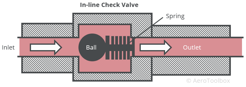
A check valve operates as a one-way valve, allowing fluid to flow unimpeded in one direction but not in the other. A common check valve uses a spring-loaded ball seated inside a housing. The spring compresses under pressure to allow flow in the desired direction. Once the flow stops (or reduces below a set rate), the ball seats in the housing, cutting off the flow.
Pressure Control Valves
Control of the pressure within a hydraulic system is necessary for the safe operation of the system. Some valves are designed to relieve pressure so that the system doesn’t reach dangerous operating pressures, while others regulate the pressure within a defined range.
There are two common pressure relief valves used in an aircraft hydraulic system. System relief valves act as a safety device against overpressure as a result of the failure of a pump, regulator or similar device. These valves are fitted directly downstream of the pump and will open at a set pressure, relieving the system by returning fluid to the reservoir.
A thermal relief valve is designed to relieve excess pressure in the system due to thermal expansion of the fluid. These valves are usually smaller than system relief valves and used where a flow control valve prevents pressure from being relieved due to the one-way nature of the valve.
A pressure regulator valve is used in a hydraulic system where a constant delivery type pump is operating. Since a constant delivery pump is unable to regulate its own pressure, a valve situated just downstream of the pump can be opened or closed to either increase or decrease the pressure which keeps the system pressure within a defined operating range. Fully opening the valve will divert all flow from the system back into the reservoir allowing the pump to turn without resistance. This is termed “unloading the pump”.
Accumulators
An accumulator provides a means to store fluid under pressure at different points throughout the system which can then be used to dampen pressure surges or supplement the pump under high operating loads. Accumulators also provide limited system operation in the event of a failure of the pump.
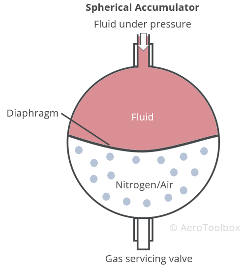
A common accumulator used in aircraft hydraulic systems is the spherical type which consists of two spherical chambers separated by a rubber or synthetic diaphragm. The top half of the accumulator is designed to accept fluid under pressure, which reacts against air or nitrogen housed in the lower half of the accumulator. The hydraulic pressure will compress the gas until the pressure in the two chambers is equal. When a hydraulic actuator is required to operate, the accumulator located nearest the actuator will feed fluid under pressure directly to the actuator, reducing the pressure in the accumulator which is then replenished by the system pump. This allows for a more rapid actuation than would otherwise be possible, eliminating any lag from the mechanical pump.
Actuators
The purpose of an actuator is to convert fluid pressure into a mechanical force that can be used to perform useful work. Work is the product of force and displacement and so applying a pressure to one side of an actuator will cause that actuator to move with a force equal to the pressure difference multiplied by the actuator’s cross-sectional area, and perform work such that energy in the system is conserved.
Linear Actuator
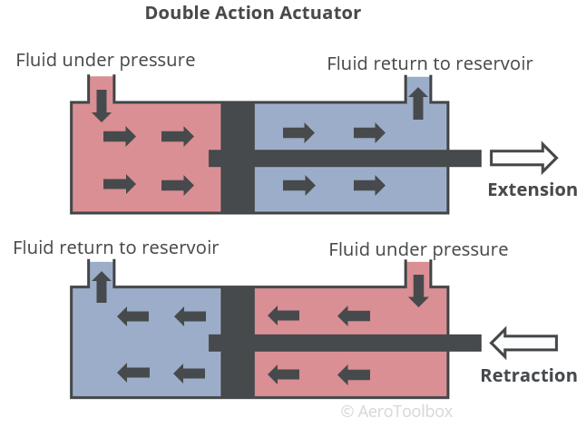
A linear actuator consists of a cylinder and piston arrangement where one side of the piston is connected to a rod which actuates depending on the pressure acting on the piston. A double-action actuating cylinder is designed to extend and retract under pressure. Fluid under pressure enters one side of the cylinder, pushing the piston and causing the lower pressure fluid on the other side of the piston to return to the reservoir. A selector valve allows the direction of motion to be reversed such that fluid under pressure can enter the previously low-pressure side of the actuator, reversing the actuator direction.
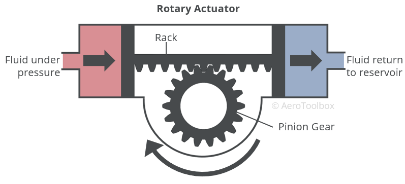
Rotary Actuator
A rotary actuator converts the pressure differential set up by the hydraulic system into a rotary motion, usually through a rack-and-pinion arrangement. This is a common arrangement used in a hydraulically assisted nose-wheel steering mechanism.