All modern aircraft are fitted with a braking system to assist in slowing and stopping when on the ground. Brakes are used not only to decelerate during a landing run, but also to hold the aircraft during an engine run-up, and in some cases to steer the aircraft through differential braking. Brakes are fitted to the main landing gear but not generally to the nose or tail wheel.
Aircraft Braking Basics
Physics of Braking
Brakes work by dissipating energy as heat through the action of friction. An aircraft wheel rotating at speed possesses a large amount of kinetic energy. By contacting the wheel with a semi-metallic or ceramic brake pad, an enormous amount of heat is generated as a result of the friction between the two contacting surfaces.
The large frictional forces generated during braking cause the pads to wear and so careful inspection and maintenance of the system is required to ensure the brakes continue to operate as designed.
Brakes are usually hydraulically actuated, but in some cases may be operated through a mechanical actuation system.
Brake Application
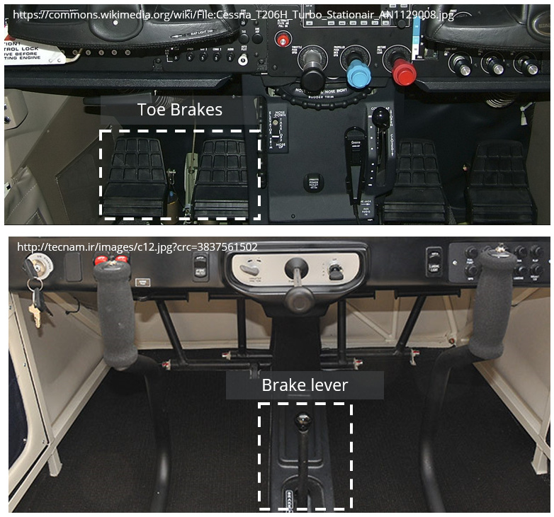
Traditionally, brakes are fitted to the upper half of the rudder pedals and are actuated through the pilot applying pressure to the top of each pedal. This toe-brake configuration is widely used and allows the pilot to apply differential braking by varying the pressure applied on each toe brake.
Many smaller light sport aircraft do not make use of toe brakes, preferring to use a simpler single lever mechanism. This lever is usually situated in the cockpit centre console and applies equal braking to all main wheels when engaged. The advantages of a single braking system include reduced complexity and lower part count when compared to toe-brakes. However, differential braking is clearly not possible with a single lever mechanism.
Most aircraft are fitted with a parking brake which can be applied through a switch or lever and will keep all brakes engaged when applied.
Types of Brakes
Disc Brakes
Disc brakes are the most common braking system in use today and consist of a disc which rotates with the wheel and a stationary brake calliper which actuates onto the disc to affect a braking force. The calliper is the name given to the assembly that contains the brake pads and piston(s). The pads are connected to the piston which actuates under hydraulic pressure applied either through a toe brake or a brake lever in the cockpit.
Single Disc Brakes
Smaller aircraft typically make use of a single disc sandwiched between two pads and attached to each main landing gear leg. The disc is fixed to the wheel so that it rotates as the wheel rotates. As the pilot applies the brakes, the calliper presses the pads against the disc braking the aircraft.
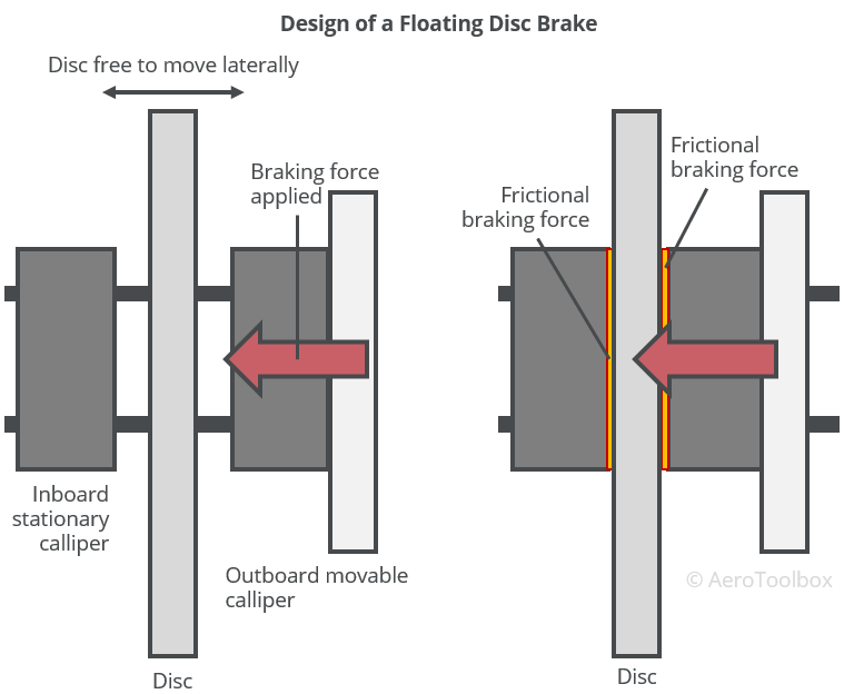
It is important that the frictional force applied by the callipers is uniform and evenly distributed. A typical braking system is designed with two callipers per disc; one calliper located on either side of the disc. The disc rotates with the wheel but is free to move laterally between the two sets of callipers. As the brakes are applied, the outer calliper moves inward towards the disc, contacting the disc and pushing it onto the inboard stationary calliper. In this way friction is applied evenly on both sides of the disc. When the brakes are released, a spring forces the piston to retract away from the disc, removing the braking action so that the disc is once again free to rotate. This disc brake configuration is called a floating disc brake as the disc is free to “float” laterally between the two callipers.
An alternate single disc arrangement used on light aircraft is the fixed disc brake arrangement. This works by fixing the disc rigidly to the wheel and allowing the callipers to move laterally as the brake is applied. Similar to the floating arrangement, this ensures that the brake pads apply an even braking force to the disc throughout the braking operation.
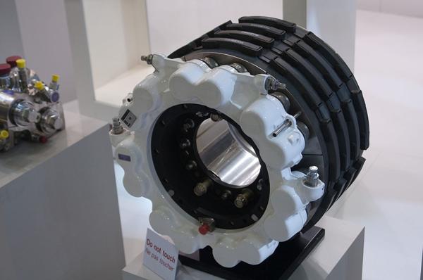
Multiple Disc Brakes
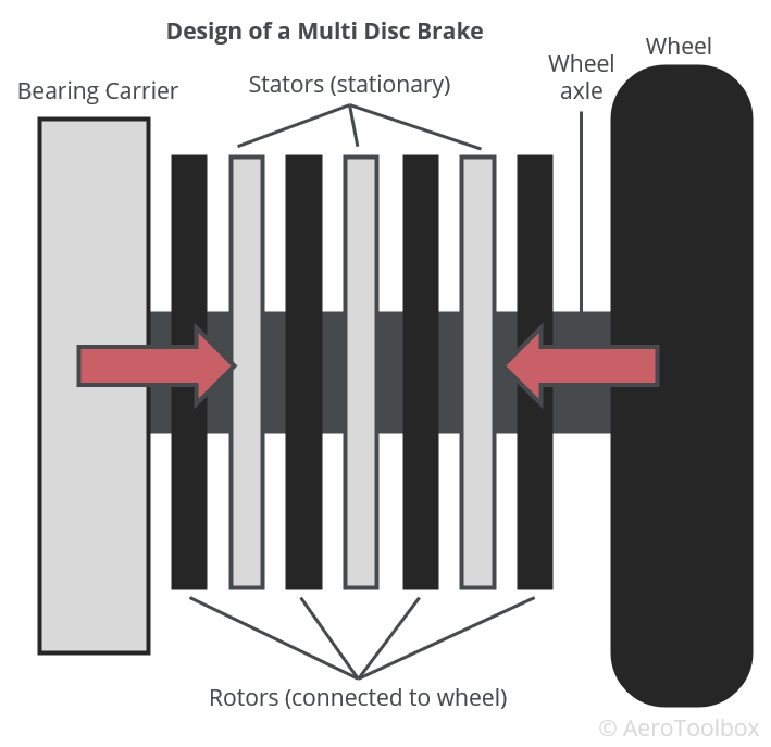
Larger, heavier aircraft with higher landing speeds are unable to extract sufficient braking force out of a single disc and calliper setup. The braking systems for these aircraft are designed with multiple sets of stationary steel discs (stators) sandwiched between copper or bronze rotors which rotate with the wheel. Hydraulic pressure applied to the stack of stators and rotors compresses the plates together, creating a large frictional force which brakes the aircraft.
The design of a multiple disc and rotor systems has been improved over the years. The current state of the art for large aircraft is a segmented rotor-disc which operates in the same manner as above but with cut-outs in the plates for improved airflow and heat dissipation.
Recent improvements of segmented rotor-disc systems includes the use of carbon composite as the primary material from which to construct the rotors. Carbon fiber has improved heat dissipation characteristics when compared to steel, is stronger than steel, and does not fade at high temperatures. Carbon brakes also require less maintenance than traditional braking systems and are set to become the standard braking material in use for high performance braking applications.
All multi-disc systems require powerful hydraulic forces to actuate and control the systems. This is accomplished through a power brake or booster system which is discussed at the end of this post.
Expander Tube Brakes
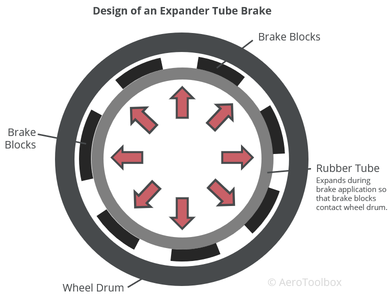
An older technology used predominantly on aircraft manufactured between 1930 and 1950, expander tube brakes are a low-pressure braking system that has now largely been replaced by disc brakes. The basic design consists of a lightweight frame attached to the outer section of a rubber tube. The frame and tube sit inside a wheel drum and a number of brake blocks are attached to the frame which provides the braking surface. The rubber tube is inflated during braking which pushes the brake pads onto the inside of a wheel drum, generating the friction necessary to slow the aircraft.
The tube is inflated through hydraulic action, where the effectiveness of the braking system can be varied through the hydraulic pressure developed. Springs installed in the system return the expander tube to its deflated position when braking force is removed by the pilot.
Brake Actuation Systems
Both disc brakes and the older expander tube type make use of a hydraulic system to actuate the brake pad onto the disc or drum. The hydraulic system that provides this actuation differs depending on the size and complexity of the aircraft. Three different systems are described below and cover the majority of brake actuations systems in use today.
Independent Brake System
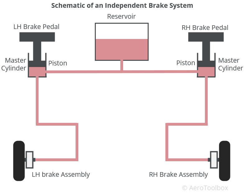
Light aircraft without a hydraulic system to actuate flaps, control surfaces, or landing gear make use of an independent hydraulic system to actuate the brakes. This stand-alone system consists of a reservoir, master cylinder connected to a brake pedal, and a piston in the brake calliper that actuates to apply the braking force.
When the pilot applies the brake pedal (independent toe-brakes or a single lever), the hydraulic fluid in the master cylinder is forced through the hydraulic lines to actuate the piston in the calliper. This pushes the pads onto the disc or drum, creating the friction necessary to slow the aircraft.
The applied braking force is a function of the force applied at the master cylinder. The harder the pilot applies the brake, the greater the braking pressure applied at the wheel. A typical braking system consists of two master cylinders (one for each toe brake) and two pistons that actuate under braking (one on each main gear leg). The reservoir may be remote and installed within the system or built into each master cylinder which removes the need for a separate reservoir unit.
Booster Brake System
An independent braking system does not make use of a mechanical pump to augment the pressure applied by the pilot by operating the brake. An aircraft fitted with a hydraulic system can boost the brake pressure by tapping the hydraulic system into the brake system. This hydraulic boost is only used under heavy braking and can increase the brake pressure to a value greater than that which can be applied by the pilot alone.
Brake booster systems are used on larger aircraft that require augmentation of the manual hydraulic braking system to slow the aircraft in a reasonable distance.
Power Brake System
Power braking systems are used on large aircraft where a manual or boosted system is insufficient to develop the hydraulic pressures required to arrest the aircraft. This system uses the aircraft’s hydraulic system as the sole source to apply the brakes. The pilot still controls the brakes through the toe-brakes on the rudder pedals, but the force produced is no longer a function of the strength of the pilot. Applying the brake opens a valve that allows fluid from the hydraulic system to enter the brake lines. The rate at which hydraulic fluid flows into the brake lines is regulated by the valve and is designed to give the pilot a “feel” for the braking action that is proportional to the force exerted on the brake pedal.


