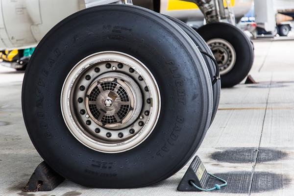
The wheels and tires (tyres) fitted to an aircraft are designed to support the full weight of that aircraft while on the ground, and transmit the static and dynamic loads generated during taxi, take-off and landing into the aircraft's shock absorption system (typically an oleo-pneumatic shock absorber or steel spring). The largest loads that the wheel/tire assembly sees occur during landing and are characterised by high speeds and large impact loads which deforms the tires, loading the wheel at the flanges. This tutorial focuses on the design and construction of the wheel and tire assembly as fitted to a typical aircraft.
Wheels
It is necessary to differentiate between the wheel and tire when discussing both components. The wheel is the name given to the cylindrical metallic structure that is connected to the landing gear axle through bearings, and is shaped to provide a seating surface for the tire. The tire is made primarily from rubber, and is the only part of the aircraft that comes in contact with the ground. Wheels are typically made from aluminium or magnesium alloy which is light and strong.
The design of a modern aircraft wheel differs from the automotive wheels that you may be accustomed to. Automotive wheels are typically manufactured as a single assembly whereas aircraft wheels are constructed in two pieces and then fastened together after the tire is installed. This two-piece construction is necessary as an aircraft tire is designed to flex in order to absorb the very large impact loads without separating from the rim. The design of a flexible aircraft tire is not conducive to being stretched over a single piece wheel like that of a car.
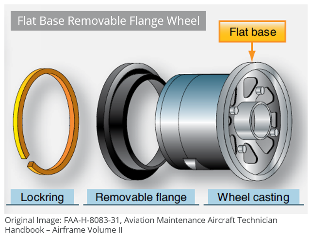
Removable Flange Wheels
Early two-piece wheels were designed similar to an automotive tire, but with a removable flange that allowed the tire to be installed easily onto the wheel and then inflated to the desired pressure.
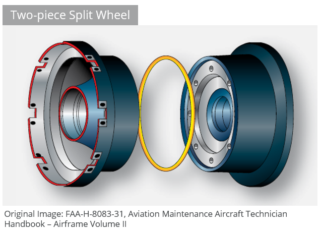
Modern Two-piece Wheel
A more modern evolution of the flange removable wheel is the two-piece wheel, where the wheel is split into two near equal halves and bolted together with an o-ring in the center to form a tight rim seal. The two flanges form the bead seating region where the tire contacts the wheel. During touch-down the tire compresses rapidly, exerting a large tensile load in the flanges. The flanges are designed to withstand this loading and also to prevent the tire from slipping relative to the wheel under heavy braking.
Inspection and Maintenance
Large loads are induced in the wheel/tire assembly during a heavy landing and excessive braking can quickly raise the temperature of the tire, increasing the pressure to a point where the tire may blow-out. Many high-performance two-piece wheels are designed to accommodate a thermal plug which is designed to melt at high temperatures, deflating the tire and preventing an explosion.
It is necessary to pay close attention to the wheels and tires during a preflight inspection. A pilot should check that all nuts and bolts are secure and that no obvious cracks or evidence of overheating are present. Tires should be checked for tread wear, correct inflation pressures and any flat spots or foreign object damage (FOD) which could cause the tire to fail during take-off or landing. The brake assembly should also be thoroughly inspected during the preflight; looking for leaks, brake lining wear, and that sufficient hydraulic fluid is present in the system.
Tires
The tire (tyre in British English) is the only part of the aircraft in contact with the ground, and a well-maintained set of tires is crucial to the safe operation of any aircraft. Tires cushion the impact on touch-down and transfer the energy of landing into the wheels.
Aircraft tires differ substantially in their operating profile to automotive tires. Car tires are load bearing for a considerably longer time than an aircraft during a typical mission profile, albeit at relatively low speeds with slow accelerations. Aircraft tires on the other hand spend comparatively less time operating but must absorb very large impact loads and handle high speeds with large accelerations when in contact with the runway. Aircraft tires are designed to flex far more than automotive tires which assists in damping the large impact loads.
Tire Classification
Tires are typically classified according to their dimensions, strength (ply-rating) and configuration (tubed or tubeless). To ensure safe operation, the correct tire should always be fitted to a particular aircraft in accordance with the operating manual.
Dimensions and Sizing
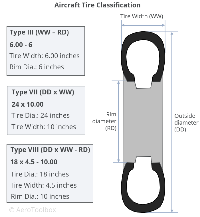
Dimensional classification is usually made according to outer tire diameter, sectional width, and the diameter of the rim. A common classification system in use today is that of the United States Tire and Rim Association, where aircraft tires are classified as one of nine types.
Today, three tire classifications cover almost all aircraft classes in use, from light aircraft up to modern jet airliners. These three classifications use a slightly different way to report the tire dimensions; this is described below.
Type III
Type III tires are common low-pressure general aviation tires predominantly used on light aircraft with reasonably low landing speeds. These tires are easily identified as they have a small rim diameter in comparison to their width. Type III tires are designated by a two-number system: the first number describes the nominal tire width and the second the diameter of the rim that the tire can be fitted to. The two numbers are separated by a dash.
Type VII
Type VII tires are high-pressure, high performance tires fitted to jet aircraft. These tires are sized according to a two-number system that differs from the Type III classification described above. Here the first number designates the nominal overall diameter of the tire while the second number, which is separated from the first by a multiplication sign, gives the nominal section width.
Type VIII
Type VIII tires are designated by three numbers and incorporate the conventions of both the Part III and Part VII tires. The first number specifies the outside diameter, the second is the nominal tire width, and the third is the rim diameter. These tires are designed to operate at high-pressures and high speeds and are the most advanced tires in use on large jet aircraft today.
Ply Rating
Ply-rating provides an indication of the relative strength of the tire. The strength of early tires was directly proportional to the number of reinforcing plies present in the design which is how the ply rating system originated. Nowadays, the use of modern materials and complex manufacturing techniques have rendered the actual ply count somewhat irrelevant when discussing to the strength of a tire. However, a ply-rating system (now decoupled from actual ply count) is still used to describe the relative strength of one tire against another and remains an important indicator of tire strength.
Tubed or Tubeless
Aircraft tires are either designed to use an inflatable tube to provide the required pressure or seal directly onto the wheel without a tube. Tubeless tires are built with an inner lining to prevent air leaks and are stamped with the word “tubeless” on the tire sidewall. Tubeless tires are lighter than tubed tires and are less susceptible to tire creep, which occurs when the tire shifts relative to the wheel during a hard impact.
Construction
A tire follows a layered construction approach where each layer (region) of the tire serves a different purpose. Broadly speaking, a tire can be divided into four specific regions: the bead, ply, tread and sidewall.
Refer to the image below which shows the make-up of a typical aviation tire.
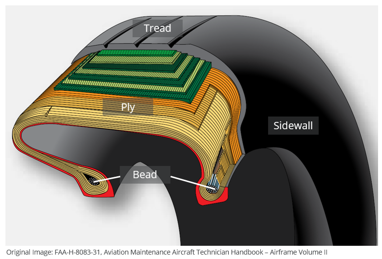
Bead
The bead consists of bundles of high strength steel wire encased in rubber. This provides the tire with lateral strength, anchoring the structural plies and transferring the impact loads generated in the tire onto the wheel rim. Tires that are designed to operate at higher speeds and at higher loads may have multiple bundles of beading to effectively transfer the loads and resist the large tire deformations that result.
Ply Region
A tire is built from multiple plies which are laid on top of each-other to give the tire its structure and form. Plies are usually manufactured from nylon fabric sandwiched between layers of rubber. These structural members are sometimes called carcass plies as they form the skeleton of the tire. The concept of ply rating refers to the relative strength of the tire’s ply layup. The ends of each ply are anchored to the beading on each side of the tire to transfer load out the tire and into the wheel.
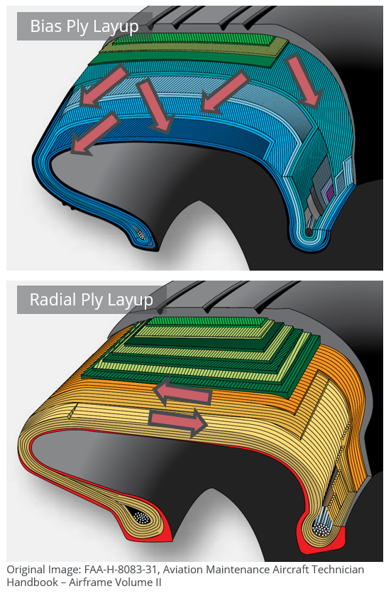
Plies are characterised according to their orientation relative to the direction of motion of the tire. Traditionally, plies were orientated predominantly in the direction of motion of the tire (with a bias of between 30° and 60°). This is called a bias ply layup as the plies are orientated with a bias to the direction of rotation. Bias plies result in a tire that is flexible and able to absorb the loads typically seen during landing and take-off.
A radial ply layup is one where the plies are laid perpendicular to the direction of motion of the tire. This results in a stronger tire, but one that is not able to deflect and flex as much as in a bias ply layup.
Tread
The tread refers to the wearable part of the tire that is designed to come into contract with the ground. The tread is located on the tire crown and must resist frictional wear, abrasion, cracking and cuts that occur as a result of the landing surface and condition of the runway.
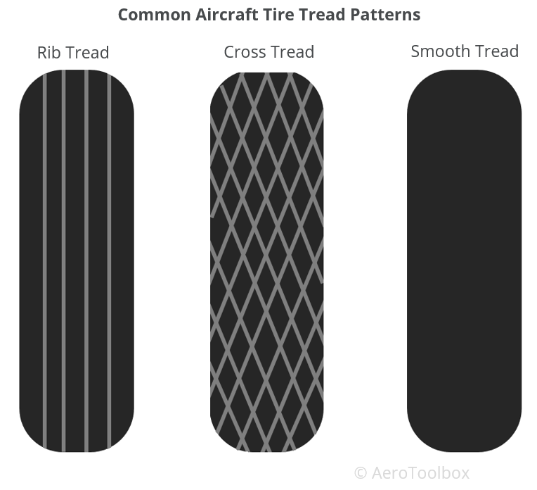
The tread pattern seen on the tire differs according to the operational requirements of the tire. Most tires are grooved in the circumferential direction which provides good operating characteristics for aircraft generally flown into and out of prepared runways. The grooves that characterize a rib tread tire assist in cooling the tire and provide a means for water to channel away from the tire in wet conditions.
Aircraft operating from unprepared or unpaved surfaces may be fitted with a cross-tread pattern. This diamond pattern is cut deep into the tire and provides more traction that the rib tread design in soft ground. On a hard surface (asphalt runway) the tire has a smaller total contact area and so will provide less traction that a tire with a rib tread.
Some older aircraft may have a smooth tread with no ribs or cut-outs. This provides the greatest traction, largest contact area, and subsequently the greatest frictional force which assists in stopping the aircraft.
Sidewall
The sidewall of a tire is designed to protect the plies (carcass) that gives the tire its strength. Information about the tire: its dimensions, speed rating, ply rating, direction of rotation, manufacturer etc is printed on to the sidewall for easy reference. The inner sidewall is covered by an inner liner which is a thin rubber liner designed to prevent damage to the carcass plies. Small vent holes in the sidewall are built-in to allow trapped air in the plies to escape. This helps prevent delaminations between plies from forming as a result of the trapped air expanding due to altitude and temperature changes.
Tire Wear and Creep
Tire Wear
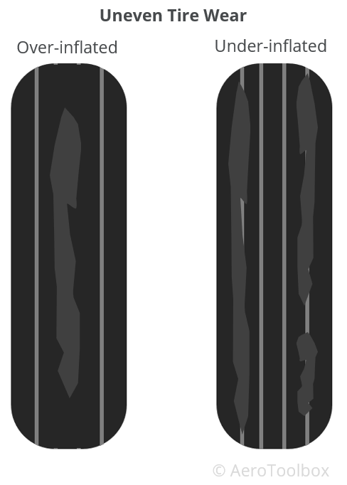
Tires that are operated at the incorrect inflation pressure result in an uneven tread wear that could be detrimental to the safety of the tire. The nature and severity of the wear can alert the pilot as to whether the tire is over or under-inflated. Considerable traction is lost when a tire has worn beyond its limits and should always be replaced or retreaded rather than left to operate in a poor condition.
A tire that is over-inflated will tend to wear towards the center of the tread. This is because at higher inflations, a smaller area of the tire is in contact with the ground and so wear is highest in this region.
Conversely, under-inflated tires will wear towards the tire shoulders as the tire sags onto the ground with a corresponding increase in friction. This can lead to the tire overheating, damage to the carcass, and the tire creeping or pinching at the sidewall.
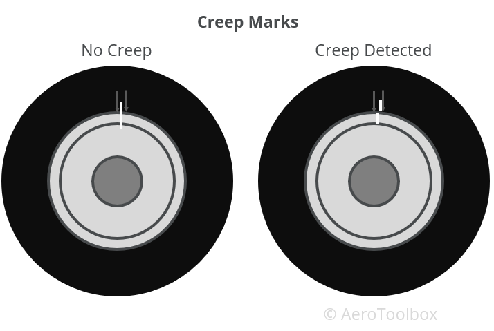
Creep Markings
Hard landings and heavy braking, particularly if the tire is under-inflated, can lead to movement of the tire relative to the wheel in the direction of rotation. Rotation of the tire around the rim is referred to as tire creep or slip and should be avoided. Creep in a tubed tire is particularly undesirable as this could cause the tube valve to rupture, resulting in a blow-out.
Tire creep is often monitored by painting a single white line over the tire and wheel once the tire is installed and inflated to the correct pressure. Any slip is easily identified as the line on the tire and wheel move out of alignment. Acceptable creep limits are established by the tire manufacturer and often creep markings are moulded into the sidewall between which the line across the wheel and tire is drawn. Once the alignment moves beyond the limits bounded by the markings, the creep is deemed too severe and must be addressed.