In the previous post on the topic of piston aircraft engines we discussed the four-stroke cycle, digging into the details of what happens inside the engine block once the engine is fired up. Now we move from under the cowling to inside the cockpit and discuss the engine instruments and controls you are likely to encounter as you take to the skies.
Typical Light Aircraft Engine Instruments and Controls
The picture below is a screenshot of a typical analogue Cessna 172 cockpit. Chances are you will begin your flying career on a similar aircraft. Most ab-initio trainers like the C172 have fixed pitch propellers where the engine speed is controlled entirely through the throttle lever: advancing the throttle increases the speed of the engine and propeller, and retarding the throttle causes the engine and propeller to slow.
The engine speed is monitored through the tachometer and the health of the engine monitored through the oil temperature and pressure, the cylinder head temperature, and the exhaust gas temperature.
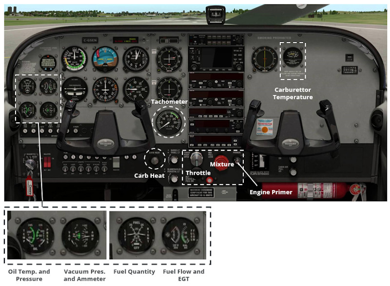
The mixture lever provides a means for the pilot to adjust the ratio of fuel to air entering the engine manifold which impacts on the ability of the engine to produce power. Pulling the mixture lever all the way out (idle cut-off) stops the flow of any fuel to the engine, causing the engine to stop. As the mixture lever is advanced, the concentration of fuel in the air-fuel mixture increases which impacts on the thermodynamic efficiency of the combustion process in the cylinder. Too little fuel entering the engine will cause combustion to cease and the engine to stop, while too much fuel entering the engine is inefficient and will result in unburnt fuel leaving through the exhaust system. It is up to the pilot to monitor the mixture and make adjustments as necessary. Higher concentrations of fuel in the mixture are termed rich mixtures and lower concentrations lean mixtures. Mixture is described as a mass ratio rather than a volume ratio as the density of air varies with temperature and altitude which causes the volume of air to change. Since the density of air varies depending on the ambient atmospheric conditions, the mass of fuel required to maintain a given mixture ratio will vary as the aircraft changes altitude. The pilot must therefore lean the mixture as the altitude increases to keep the mixture ratio constant, remembering to enrich the mixture before descending to a lower altitude. Mixture setting is discussed in greater detail in the post dedicated to fuel and fuel systems but at this point it is important to be able to identify the mixture and throttle levers, and to have a basic understanding of their use to control the engine. Mixture levers are colored red by convention, pitch levers (not shown in the cockpit image) are blue, and the throttle is colored black.
Let’s now look at some of the common engine instruments found in a typical light piston aircraft.
Tachometer
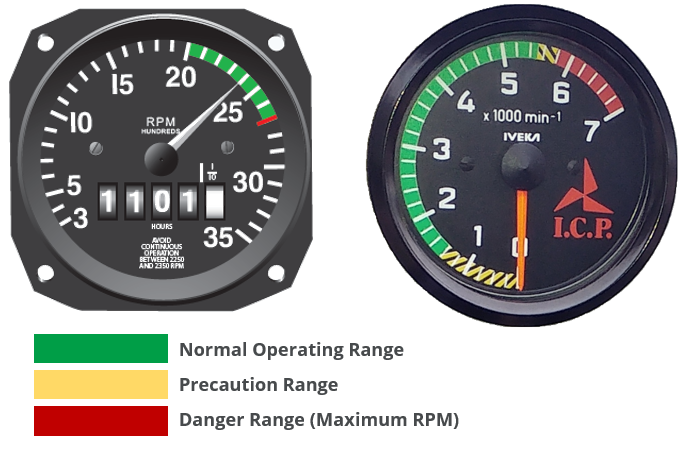
A tachometer measures the speed of the engine in revolutions per minute (rpm). Readings of engine speed are usually taken at the engine crankshaft and so do not necessarily measure the rpm of the propeller. Many aircraft engine and propeller combinations are ungeared, such as the Lycoming O-320 engine range used on some Cessna 172 models, and in these cases the engine rpm and the propeller rpm will be the same. Many newer light sport aircraft, such as the Tecnam P-92 Echo, use a smaller displacement Rotax engine which operates at a higher speed, and must therefore be geared down between the crankshaft and the propeller. A typical gear ratio on a Rotax 912 ULS engine is 2.27 such that at the maximum continuous operating speed of 5200 rpm, the propeller rotates at 2300 rpm. This is very similar to the maximum operating speed of a more conventional engine such as the O-320.
The tachometer is color-coded to indicate the operating limitations of the engine. The normal operating limit is always colored green, while maximum operating speeds are colored red. Some instruments also have a yellow band which indicates a precautionary range; here the engine should only be operated for a short period (typically 5 min) before resuming operation in the green band.
Manifold Pressure
The manifold pressure gauge provides a measure of the absolute pressure of the fuel-air mixture inside the intake manifold of the engine. The gauge is usually calibrated in inches of mercury and always reads a value less than the atmospheric pressure as the engine sucks air and fuel into the cylinder during operation. The fuel in the tanks is at atmospheric pressure (in a light aircraft) and so in order for fuel to travel into the engine it must be sucked through the fuel lines and into the carburetor or injectors.
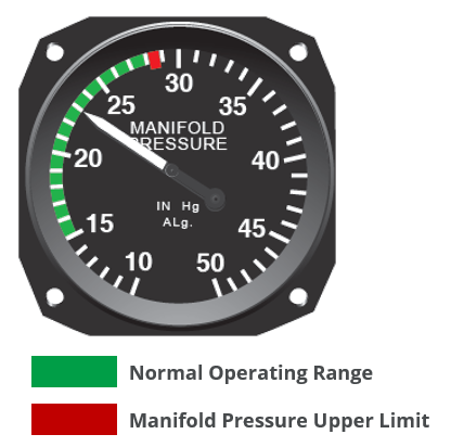
An aircraft with a fixed pitch propeller (the angle of the propeller blades is fixed before flight) does not need a manifold pressure gauge as the engine speed alone is a sufficient indication of the power being produced by the engine (higher rpm indicates greater power). However, once the pilot is able control the pitch of the propeller during flight, the tachometer no longer serves as a good indicator of the power being produced. Setting the engine power is then accomplished using both the tachometer and manifold pressure gauge concurrently.
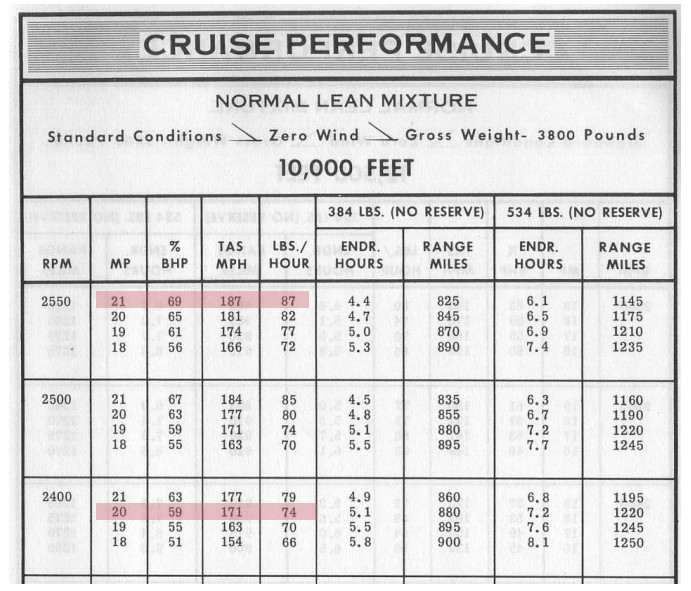
The image below is an extract from a Cessna 210 Pilot Operating Handbook where various acceptable engine speed and manifold pressure combinations are given for a flight conducted at 10 000 ft. As an example, a pilot may choose to fly at an engine speed and manifold setting of 2400 rpm @ 20’’ which should produce a true airspeed (TAS) of 171 mph burning 74 lbs/hr of fuel, or alternatively at a higher power setting of 2550 rpm @ 21’’ which will result in a TAS of 187 mph but will burn 87 lbs/hr.
When the engine is not running the manifold pressure gauge will indicate the current atmospheric pressure. Engine failure or loss of power is therefore indicated by an increase in the manifold pressure towards ambient conditions.
Oil Pressure and Temperature
Internal combustion engines require lubrication in order to operate without seizing. This lubrication is provided by the oil system and consists of a store of oil either in the base of the engine (wet sump) or external to the engine (dry sump). The oil is pumped through the engine under pressure, lubricating the engine’s moving parts. A failure of the engine lubrication system could result in the engine seizing. It is therefore vital to monitor the temperature and the pressure of the lubrication system throughout any flight to ensure safe engine operation.
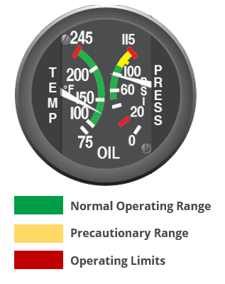
The oil pressure gauge measures the pressure of the oil at some point in the system upstream of the oil pump, and provides a means to gauge the proper working of the oil pump.
The oil passing through the engine heats up rapidly due to the high temperatures in the engine. This increase in oil temperature causes a reduction in the viscosity of the oil which means that the oil is able to flow more easily but loses some of its lubricating ability. For proper engine operation the oil must be kept within a certain viscosity range which corresponds to a particular temperature band. Aircraft lubrication systems are fitted with an oil cooler, located upstream of the oil pump but downstream of the engine. Hot oil flows through the cooler, reducing the temperature of the oil before it re-enters the engine. The oil temperature gauge is most often fitted between the cooler and the engine and so provides a measure of the temperature of the oil before entering the engine.
If the oil temperature or pressure is outside of the normal operating range, there is likely a problem with the engine’s lubrication system. This is a potentially serious condition and so the best course of action is usually to land immediately at the nearest airfield where the issue can be addressed safely on the ground.
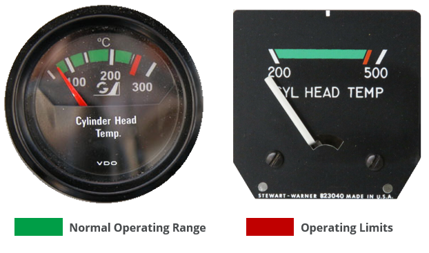
Cylinder Head Temperature
The temperature in the engine is measured by a thermocouple located in the head of the hottest cylinder and displayed on the Cylinder Head Temperature (CHT) gauge in the cockpit. This provides a direct and immediate indication of the temperature inside the engine, which must remain within a particular band during all stages of flight.
Internal engine cooling is provided by the oil system, however the high temperatures seen in the cylinders as a result of the combustion process must be dissipated. Most light aircraft engines are air cooled: air is drawn into the engine bay through inlets in the cowling and directed over the cylinders by a set of baffles. The external surface of each cylinder is fitted with a number of fins, which act as heat sinks, dissipating the heat into the air.
The effectiveness of this cooling arrangement is monitored in the cockpit by referring to the CHT gauge and ensuring that the engine remains within the normal operating band.
Different flight conditions can cause the cylinder head temperature to rise or fall. For example, a prolonged climb at a high power setting can cause the engine temperature to increase and the attitude of the aircraft during the climb may be such that the air cooling is insufficient to keep the cylinder head temperature in the normal operating range. In this instance the climb attitude should be reduced until the temperatures are back in the green band. Alternatively, a step climb could be adopted with periods of level flight to keep the temperatures down.
Periods of operation on the ground where the airspeed is low and air-cooling effectiveness is reduced can also cause the CHT to rise.
Conversely, in the case of a rapid descent where the airspeed is increased, the additional flow of air over the cylinders could cause shock cooling which should also be avoided.
Operating the engine at temperatures above the normal operating limit can cause a loss in power, detonation (premature combustion), and excessive oil consumption. Damage to the cylinder walls, pistons and piston rings and valves may also occur if care is not taken to operate within the engine limits.
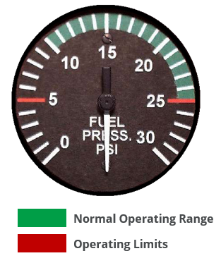
Fuel Pressure
Fuel is stored in tanks (usually in the wings) and must be delivered to the engine during operation. The fuel is pumped (or gravity fed) under pressure from the tanks to the engine. It is important for the pilot to monitor the fuel pressure to ensure that a continuous stream of fuel is being supplied to the engine. Fuel delivery is such a critical system that aircraft which require a pump to transport the fuel from the tanks to the engine are fitted with a backup pump system in the event that the primary pump fails. If the fuel pressure begins to drop during flight, the backup pump can be used to increase the pressure. The backup pump is also usually activated during critical phases of flight such as take-off and landing to add some redundancy to the system and lessen the chance of an engine failure.
The fuel pressure should be monitored during flight and kept within the green normal operating range at all times.
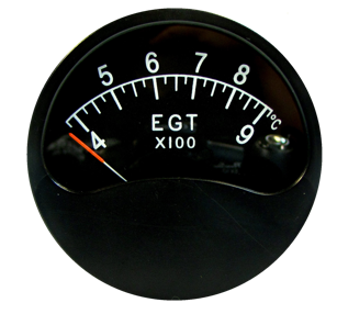
Exhaust Gas Temperature
The temperature of the gas leaving through the exhaust manifold after combustion is important to the pilot as it provides a means to adjust the ratio of fuel-to-air (mixture) to an optimum setting. The exhaust gas temperature varies with the ratio of fuel-air entering the cylinders such that as the mixture is leaned (less fuel in a given mass of air) the exhaust gas temperature (EGT) increases to a maximum before a sudden drop-off. This is significant as the peak temperature is always reached at the same ratio of fuel and air.
The EGT is hotter at leaner mixtures which indicates a more efficient combustion process where less unburnt fuel exits the cylinders through the exhaust system. During cruise the mixture is leaned using the EGT gauge by reducing the mixture to a point where EGT peaks and then enriching slightly to reduce the temperature in accordance with the aircraft flight manual. It is advantageous to lean the mixture in the cruise as this reduces the fuel consumption and allows the engine to operate at its most efficient state.
Common Faults During Engine Start
Starting an aircraft engine can sometimes be tricky – especially on a cold day or if the engine hasn’t run in a while. Let’s look at some of the more common issues seen during start up.
It is important to always follow the correct start procedure as detailed in the aircraft’s operating handbook. This will assist in prolonging the life of the engine and should result in fewer maintenance issues over the life of the engine. Below are a few common mistakes made by newer pilots and the course of action that should be taken to remedy the situation. Remember that the advice given here is general and the aircraft flight manual should always be consulted first when faced with these situations.
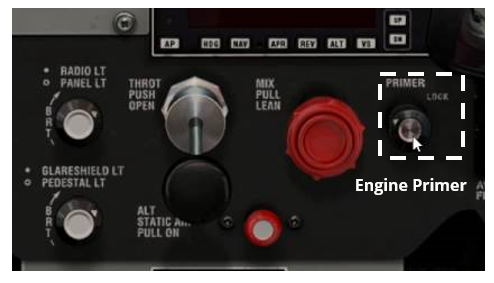
Priming
Most aircraft engines require priming before start. This involves spraying fuel into the induction system of the engine close to the inlet valve. This additional fuel serves to enrich the mixture during the start process which helps the engine to fire and run smoothly as it starts. Many aircraft have a dedicated engine primer, usually situated near the throttle and mixture controls. Using this primer ensures that additional fuel enters the engine when and where it is required.
A common (incorrect) technique that many pilots use to prime the engine is to pump the throttle prior to, or during the start. This does provide additional fuel to the engine, but the fuel ends up in the venturi of the carburetor where it is not needed rather than the inlet port where it is. This accumulation of fuel in the venturi is known as pooling and can lead to an engine fire if there is a backfire during start.
You should always follow the priming procedure as detailed in the aircraft flight manual to ensure safe and consistent starts.
Flooding
A poor or incorrect priming technique can quickly lead to a situation where there is too much fuel sitting in the cylinders for ignition to occur. When this situation is reached the engine is said to be flooded and requires a modified start procedure to correct the situation and get the engine running correctly.
A common technique to start a flooded engine involves closing the mixture completely (so no additional fuel can enter the cylinders) and turning the engine over with the magnetos (ignition system) on. The throttle position during a flooded start varies from manufacturer to manufacturer so consult the operating manual before attempting to start a flooded engine.
Cranking the engine puts a large load on the starter motor which could overheat if used for periods longer than 20 seconds. If you are struggling to start the engine you may need to wait a minute or two between starting attempts to allow the starter motor to cool. As the engine fires you should advance the mixture lever forward to ensure continued delivery of fuel to the engine.
Standing Engine
Engines that have been standing for a while tend to accumulate a thin film of oil on the cylinder walls. This film of oil is typically more prevalent on older engines where the seal between the piston rings and cylinder walls are typically worn. If this is the case then during the compression stroke of the start, the oil, which is incompressible, causes a hammer-like effect on the piston. This can cause severe damage in the form of a bent connecting rod or a cylinder head rupture. This phenomenon is known as hydraulicing and can happen on all engine layouts, but is most often seen on radial engines where a number of the cylinders are inverted, allowing oil to seep into the cylinder more easily.
To prevent hydraulicing, the propeller should be turned over a few times by hand (with the ignition system off) to remove this layer of oil. If it is very difficult to turn the engine over and lots of oil is suspected to have seeped into the cylinders then it may be necessary to remove the spark plugs and to drain the oil from the cylinder before attempting to start the engine. Once the engine is running the pilot must continuously monitor the engine instruments to ensure that it is running as it should. The next section describes some of the common issues seen once the engine is running, and what to do if you ever experience any of these.
Common Faults After Engine Start
Once the engine has started it is important to check that the oil pressure rises within 30 seconds of the start. A low oil pressure could indicate that the oil pump has failed which could result in the engine seizing due to insufficient lubrication. In this case the engine should be shut down immediately.
Here are a number of other common faults seen after engine start that a new pilot should be aware of.
Smoke
Generally, when smoke is seen in the exhaust gasses leaving the engine it is either blue or black.
Blue smoke is caused by burning oil which is an indication that oil is seeping into the combustion chamber. This is indicative of worn piston rings.
Black smoke is an indication that the mixture setting is too rich and excess unburnt fuel is ending up in the exhaust. This is also seen immediately after start if the engine has been over-primed. To correct this one should lean the mixture temporarily until the engine begins to run smoother, thereafter the mixture can be enriched again. If the engine continues to produce black smoke after the start it could also be an indication that the primer pump is unlocked, which would continue to draw additional fuel into the combustion chamber.
Rough Running due to Fuel Starvation
A rough running engine could be an indication that the incorrect mixture setting has been applied to the engine as the engine is not receiving the correct ratio of fuel to air. Alternatively, it could also indicate that a blockage exists between the fuel tank and the intake of the engine or that the fuel pump is not providing adequate pressure. The first step to troubleshoot a rough running engine is to select another tank to run off – if the problem then goes away you will know that the fault lies between that tank and the inlet manifold. You can also engage the auxiliary or backup fuel pump to see if that corrects the issue. If this improves the running of the engine, then this indicates a fault in the mechanical fuel pump.
Magneto Faults
A light aircraft’s ignition system consists of two independent magnetos each providing a high voltage to a separate set of spark plugs located in each cylinder head. It is important to test the functioning of each magneto system during the pre-flight run-up as any fault in either system should be identified while still on the ground rather than once airborne. Each system is checked by advancing the throttle to a suitable rpm and then cycling through each magneto comparing the resulting rpm to the rpm seen when both magnetos are running together. If the drop on either magneto is greater than what is allowed by the manufacturer, the flight should be terminated, and the problem investigated before flying the aircraft again. A faulty magneto should present as a rough running engine and should be easily identified by performing the magneto drop test described above. If there is no drop seen when cycling the magnetos, it may be that one of the magnetos is failing to ground itself. This is a potentially dangerous situation as the ignition system may remain live even after being turned off in the cockpit.
Fouled Spark Plugs
Fouling of the spark plugs is caused by excessive carbon build up at the firing end of the plug. This disrupts the normal working of the spark plug by redirecting the high voltage away from the tip. This can result in an insufficient voltage difference being produced between the central and ground electrode, which may cause the spark plug to stop producing sparks correctly. The symptoms of fouled spark plugs are a rough running engine and a magneto drop greater than that allowed by the manufacturer during the engine run-up test.
If large magneto drops are seen during the run-up test, then one possible solution is to lean the mixture to increase the EGT and run the engine at a high rpm for a short period of time. This has the effect of burning away the residual carbon off the plugs. After running the engine at a lean mixture setting, repeat the run-up and check the rpm drop between the magnetos. Only continue the flight if the magneto drop is within the manufacturer’s specification.
Carburetor Icing
The functioning of the carburetor is covered in greater detail in this post and is only introduced here. The carburetor uses the principle of a venturi to introduce and atomize the fuel into the air before the air-fuel mixture enters the engine. A venturi works by reducing the area through which a volume of air can flow which results in an increase of the velocity through the venturi throat (narrowest section). This increase in velocity results in a decrease in pressure and a decrease in temperature at the throat. Liquid fuel is added at the throat and evaporates instantly to form a gaseous air-fuel mixture. This evaporation requires energy to complete (latent heat of evaporation) which lowers the temperature at the throat even further.
In the right ambient conditions this drop in temperature in the venturi throat can cause the air passing through the throat to fall below freezing and any water vapour in the air can freeze onto the side of the throat, reducing the area through which the air-fuel mixture can pass. This has the effect of reducing the power that can be produced by the engine, and in severe cases can cause the engine to fail.
To combat carburetor icing, hot air is ducted from the engine to pass over the venturi when the carb heat is applied from the cockpit. This will melt any ice that has formed, and the engine should cease to run rough. Application of the carburetor heat will result in an initial decrease in engine rpm or manifold pressure before increasing again as the ice melts.
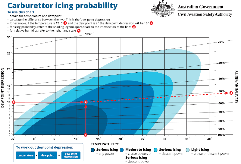
Carburetor icing can occur through a large range of temperatures but is most prevalent when the outside air temperature is between -10° C and +10° C (15° F to 50° F) and the humidity is high. The carburettor icing probability chart published below shows that icing can occur over a wide range of atmospheric conditions and as such carb heat is usually applied during the circuit to land to prevent any unplanned engine stoppages in such a critical phase of flight. Fuel injected engines do not have a carburetor which negates the need for a carburetor heating system.