The electrical system is essential to the proper functioning of any modern aircraft and is responsible for running everything from the lights and avionics, to the auxiliary fuel pump and engine starter motor.
In this three-part mini-series we will investigate the electrical system in more detail. In part one we start with an overview and discussion of the layout a typical electrical system seen on a light aircraft, and the various components that make up this system.
Part Two is focused on the theory behind electricity generation and focuses the DC generator and AC alternator.
Part Three is dedicated to batteries and the chemical process behind the working of a typical lead-acid aircraft battery.
Introduction and System Overview
The electrical system installed on an aircraft comprises of two electrical sources: a battery which is primarily used to operate the system when the engine is not running, and an alternator (or DC generator), which runs off the engine and is designed to provide a continuous supply of electricity to power the various electrical components and charge the battery once the engine has started. It is essential that the aircraft be self-sufficient with respect to its electrical requirements, as a battery has a finite capacity and will discharge as it is used. A generator or alternator installed on the aircraft can both supply the electrical components and charge the battery – ensuring that there is always sufficient battery capacity to start the engine on the next flight.
Typical Electrical System Layout
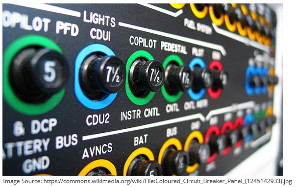
A simplified circuit diagram showing the layout of a typical light aircraft electrical system is shown in Figure 1 below.
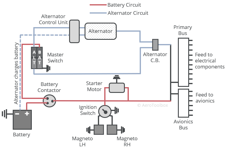
There are two circuits that feed electrical current to all electrical components: the battery circuit and the alternator circuit. All the electrical components are fed via a busbar which provides a common distribution channel to the installed electrical components.
The battery is connected to a master switch which when turned on will feed battery power directly to the busbar, powering any electrical components that are turned on. For example, turning on the master switch and rotating beacon light will route electrical energy from the battery to the beacon via the busbar.
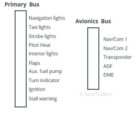
The battery is connected to the engine starter motor and is used to turn the engine over when starting. It is very important to ensure that all avionics installed in the aircraft are turned off before starting the engine as the large current draw to the starter motor could damage the sensitive radios and navigation equipment if left on during the start. On some aircraft the avionics components are wired to a separate avionics busbar which can be turned on and off via an avionics master switch located in the cockpit. If the avionics are not wired to a common bus, then each component should be manually switched off prior to start.
An engine-driven alternator uses the principle of electromagnetic induction to generate a constant supply of electricity once the engine is running. This generated electricity is then routed to the busbar where it feeds into the electrical system and runs the various electrical components operated during flight. The alternator also charges the battery while the engine is running. A Direct Current (DC) system is used to power the electric components on an aircraft; an alternator produces an Alternating Current (AC) and so must be converted to DC via a rectifier before entering the busbar. The AC alternator and DC generator are covered in more detail in the next post in this series.
The proper functioning of the generation system is monitored through a cockpit mounted ammeter or loadmeter.
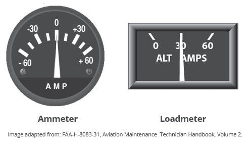
An ammeter shows the current flow into or out of the battery. The instrument is designed with a zero point in the center of the dial, and a negative and positive charge indication on either side. A positive current reading on the dial shows that the generation system is charging the battery (more current is flowing into the battery than out of the battery). A negative reading is interpreted as the battery discharging; that is, more current is leaving the battery than can be replaced by the alternator. If this is allowed to persist then the battery will eventually discharge completely. An ammeter will initially show a high rate of charge (positive reading) as the battery is recharged after the engine start. This should gradually reduce as the battery reaches full charge.
An alternative to the ammeter is a device called a loadmeter. This dial has a scale beginning at zero and shows the output of the alternator. During normal operation the loadmeter will show the sum of the load required to run the active electrical components and the load required to charge the battery.
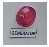
In the case of an in-flight alternator failure, the battery will continue to run the electrical components until the battery charge is depleted. In some aircraft a generator malfunction light will illuminate if the generator/alternator is no longer producing the electricity required to run the system. It is sensible to immediately turn off all non-critical electrical components if a generator failure is detected. This will reduce the drain on the battery, allowing the critical electrical components to function for as long as possible. It is advisable to terminate the flight as soon as safely possible is an alternator failure is detected.
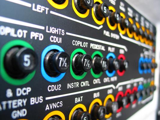
Circuit Breakers and Fuses
Circuit breakers and fuses provide a means to protect the sensitive electrical equipment from current spikes that would otherwise damage the component. Both a circuit breaker and a fuse are designed to break the circuit if a particular current load is reached. The primary difference between the two is that circuit breakers can be re-set in situ, while fuses must be replaced once triggered.
Circuit Breakers
A circuit breaker is designed to trip at a set current draw and can be manually reset each time it does. A metallic element is built into the breaker that will expand and contract as a result of the temperature change associated with increased or decreased current flow. An increased current flow will cause the element to heat up and expand, and once the critical current is reached, this expansion is sufficient to force open a set of contacts in the breaker, causing the circuit to break.
The breaker button will pop open in such a manner as to be visible to the pilot and can be reset by pushing the button back down, closing the circuit.
Circuit breakers are labelled with the current draw that will cause the breaker to pop. It is important to install a breaker with the correct current grading to properly protect the sensitive electronic equipment. Using a breaker with a limit higher than specified for a particular piece of equipment will not protect it in the event of a current surge. Conversely a breaker with a lower limit than specified for that equipment may result in unnecessary trips during normal operation.
Fuses
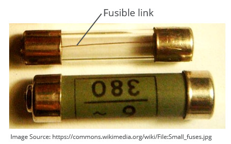
A fuse operates in a similar manner to a circuit breaker in the sense that the fuse will break the electrical circuit once a specific current draw is reached. A fuse is constructed by installing a small element of conductive material between two end caps. This material, or fusible link, is designed to melt when exposed to a current greater than or equal to the fuse design limit. This automatically breaks the circuit, protecting the equipment downstream of the fuse. Fuses are not reusable as the high current destroys the fusible link. It is important to carry a set of extra fuses when flying an aircraft designed with a fuse protection system so that the fuse can be replaced if it blows mid-flight. Similar to a circuit breaker, installing a fuse with a higher rating than specified will not adequately protect the equipment from a current surge. A blown fuse should always be replaced by one of the correct grading.
Switches
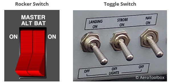
Switches are installed in the cockpit to open and close specific electrical circuits; thereby powering up or down the electronic equipment wired to that switch. Switches either close to complete a circuit or open to break a circuit.
Switches can control one circuit or multiple circuits depending on their design.
A switch is specified according to poles and throws.
- The number of poles on a switch defines the number of separate circuits the switch can control.
- The throw-count of the switch defines how many positions each of the switch’s poles can be connected to.
The simplest type of switch is a single-pole, single-throw switch (SPST). This switch controls a single circuit and is either on (closed) or off (open). A good example of a SPST switch is a landing light switch which is either set on or off.
A single-pole, double-throw switch (SPDT) controls a single circuit but has three distinct states: e.g. on, up, and down. An example of a SPDT switch may be an electrically operated flap lever that can extend (1) or retract the flaps (2) and remain off (3) when not operating.
A double-pole, single-throw switch controls two circuits which each have two states A good example of a DPST switch is a split master battery and alternator switch. Each circuit (battery and alternator) is controlled by the switch and each circuit has two states (on and off).
Electrical Faults and Remediating Actions
Electrical failures generally can be classified as one of two issues:
- The battery is flat or there is insufficient charge to start the engine.
- The alternator or generator is faulty and so does not provide the necessary electricity to run the electronic systems and charge the battery.
In all cases the first step when diagnosing the problem and attempting to correct it is to perform a thorough check of all the circuit breakers or fuses to ensure that no circuit breakers have popped, or fuses blown.
If there are no popped circuit breakers then the health of the battery can be assessed by checking the voltage over the two terminals – either through a voltmeter gauge installed in the cockpit or manually at the battery using a multimeter. Knowing the nominal battery voltage can help you to determine if the battery is flat. Starting the engine requires a high current draw from the battery and so if the battery is flat it may not be possible to start the engine.
You can also check the battery terminal connections to see that they are seated correctly on the battery (if still on the ground). A loose connection with poor contact could be the reason for the electrical fault.
If the battery shows a full charge and the electronic components are working, but the engine won’t turn over, then the fault may be with the ignition system or starter motor. This should be assessed by a licensed aircraft mechanic before the aircraft is released back into service.
Finally, a failure in flight of the alternator is identified by a discharge on the ammeter or the illumination of the generator warning light. This will lead to a situation where the electrical system will stop working once the battery fully discharges. If this occurs in flight, and there are no blown fuses or open circuit breakers, then it is sensible to reduce the electrical load as far as possible by switching off all non-essential electronic components. It is not wise to continue a flight with a failing electrical system and so diverting to the nearest safe landing strip may be the best option. It is worth reiterating that the aircraft ignition system is separate from the electrical system so the engine will not stop, even during a full electrical failure.
This brings us to the end of this tutorial. The next tutorial in this mini-series focuses on electricity generation in an aircraft, focusing on the theory and design of the engine-driven alternator/generator. As always, if you enjoyed this post or found it useful as a study aid then please let your colleagues and friends know about AeroToolbox.com, and share this on your favourite social media platform. Thanks again for reading.


