Welcome to part two in a three-part mini-series focusing on the aircraft electrical system. In the previous post we introduced the electrical system and discussed the layout and components that make up a typical light aircraft electrical system.
A conventional aircraft electrical system consists of a battery used primarily to power the system when the engine is not running, and an engine driven generator which provides a continuous source of electricity once the engine has started. The focus of this article is the engine driven generator/alternator.
In part three we explore aircraft batteries in more detail and discuss the chemical process that converts chemical energy to useful electricity in a lead-acid battery.
Fundamental Principles of Electricity Generation
In order to discuss the theory behind an electrical generator we first need a working knowledge of the principles behind electric charge and electromotive force. This requires that we start at the atomic level by looking at the components that make up an atom.
The Atomic Model
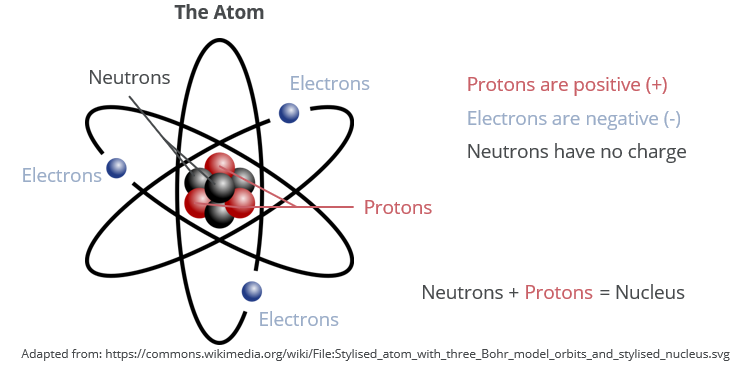
All matter is made up of atoms. An atom is so small that a typical 70 kg human being is estimated to be made up of \( 7\times 10^{27} \) atoms! That is seven billion billion billon! Every atom consists of protons, neutrons, and electrons. In the center of the atom is a dense nucleus which contains protons (positive charge) and neutrons (no charge). The nucleus contains 99.94 % of the total mass of the atom.
Electrons (negative charge) orbit the nucleus and are attracted to the protons in the nucleus by an electromagnetic force. It is this force which keeps the electrons bounded to the atom; however, electrons can detach from the atom and move to another atom under the influence of an external electromagnetic force. It is this movement of electrons that underlies the principle of electricity.
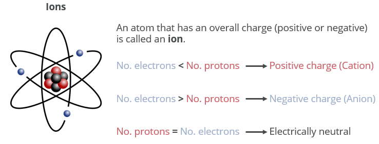
Every atom has three charge states: positive, negative, neutral, based on the number of electrons present relative to the number of protons in the nucleus. An atom with a greater number of electrons than protons will have a negative charge, while an atom with fewer electrons relative to the number of protons will be positively charged. A charged atom is termed an ion. Remember that it is the electrons which can move from one atom to the next, and not the protons. The number of protons in an atom remains constant and the ion’s charge is dictated by the number of orbiting electrons.
- An atom with a positive charge, has a deficit of electrons, and is called a cation.
- An atom with a negative charge, has a surplus of electrons, and is called an anion.
Electromotive Force (EMF)
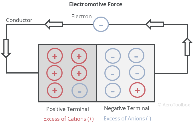
The surplus electrons orbiting the nucleus of a negatively charged anion tend to want to flow to a region where a deficit of electrons exists (positively charged cations). If a suitable conductor is placed between regions of negative and positive charge, the electrons will separate from the negatively charged anions and flow through the conductor to the positive ions; such that the charge difference is equalized.
This electron flow is known as electromotive force (emf) and can be thought of as the output from a battery or electrical generator. Emf is measured in volts and represents a potential difference between two points (e.g. the two terminals in a battery).
It is this potential difference, or voltage, that drives the flow of electrons through a conductor to form an electric current, thereby producing electricity.
Ohm’s Law
There are three primary variables when working with electric flows: voltage, current and resistance. We will define each now, and then show how they are related through Ohm’s Law.
Voltage
We have already touched on voltage in our discussion on emf. It is perhaps best thought of as a measure of the available electrical “pressure” that can be used to drive electrons around a circuit. The analogy between potential difference (voltage) and water pressure is often used to describe voltage. A water tank situated on the roof of a building with a closed outlet valve has a certain amount of water pressure, which if the valve were opened, would cause the water to flow under the influence of gravity. A battery is the electrical equivalent of this water tank. There is a certain potential difference (voltage) between the terminals of the battery, which if allowed to flow through a conductor will do so until the voltage (pressure) is equalized.
Current
The rate at which electric charge flows is defined as the current. Current is measured in Amperes (often abbreviated as amps). The rate of flow (current) is a function of the potential difference, and the resistance to the flow.
Current flow has to do with the movement of electrons from a region of electron surplus (negative terminal) to a region of electron deficiency (positive terminal). This direction of movement of electrons from the negative terminal to the positive terminal is termed electron current and is opposite to the standard convention used when analyzing electric circuits.
Conventional current is arbitrarily defined as moving from the positive terminal to the negative terminal and is most often used when performing electrical circuit calculations.
Resistance
Every electrical conductor is characterized by some level of opposition (resistance) to the flow of electrons through it. In the same way that the air resists the motion of an aircraft, causing drag, so a conductor resists the flow of charge (current) through itself. The greater the opposition to this flow, the larger the resistance. Resistance is measured in Ohms.
- Copper wire allows electrons to pass through it easily and so makes a good conductor and has a low resistance.
- Tungsten wire (lightbulb filament) provides a high resistance to the flow of electrons, is a poorer conductor than copper, and as a result of its high resistance glows red hot, providing light in the dark.
Ohm’s Law
Ohm’s law relates the voltage, current and resistance in a circuit to one-another. The law states that the current through a conductor between two points is directly proportional to the potential difference across the two points, and inversely proportional to the resistance. This can be represented mathematically as the relationship:
$$ I = \frac{V}{R} $$
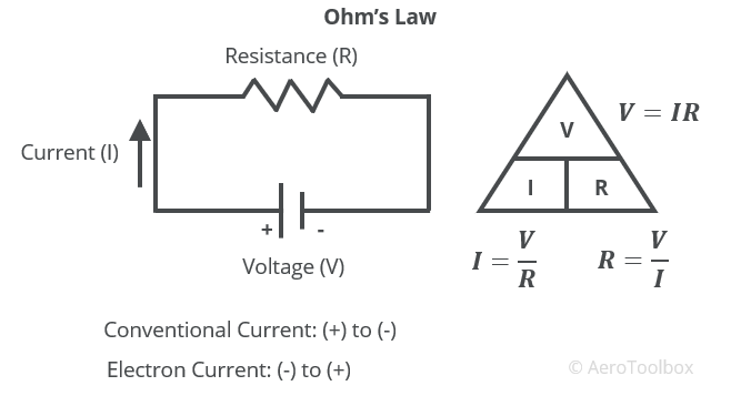
Knowing any two of the three variables, the third can always be determined.
Magnetism and Electromagnetic Induction
Magnets
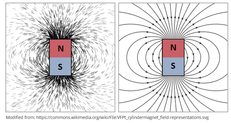
The field set up around a magnet is central to the generation of electricity through a process known as electromagnetic induction.
A magnet can be described as any material that attracts iron and induces a magnetic field around it. Every magnet contains two poles (North and South), and the magnetic field set up around a magnet is characterized by lines of magnetic flux that leave the magnet at the north pole and enter again at the south pole.
Electromagnetic Induction
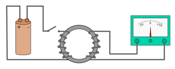
In the early 19th century Danish scientist Hans Christian Oersted discovered a link between magnetic fields and electric currents. He showed that a compass needle is deflected by a current carrying wire when cycling current through the wire. Further work by Michael Faraday in 1831 demonstrated the phenomenon of electromagnetic induction. Faraday was able to induce a current flow through a conductor by changing the magnetic field around the conductor. His experiment involved wrapping two wires around opposite sides of an iron ring (called a torus) and then closing a switch to allow current to flow through the wire wrapped around the left-hand side of the iron ring. He then observed that even though the right-hand circuit was completely disconnected from the left-hand circuit, when the battery was connected and disconnected, there was a flow of current induced on the right-hand circuit.
The relationship between a changing current and changing magnetic field forms the underlying principle in the generation of electricity. By moving an electrical conductor through a magnetic field, a current can be induced in the conductor which can be used to run electrical systems or charge a battery.
The direction of motion of the conductor in a stationary magnetic field is critical to the establishment of a current flow and emf across the wire. A conductor moving parallel to the direction of the magnetic field will induce no current in the wire. The conductor must cross the magnetic field at right angles to the field in order for current to flow.
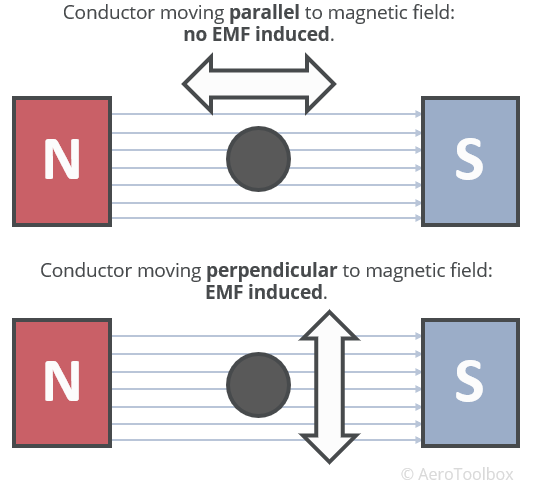
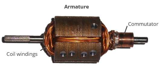
An efficient means to ensure that the conductor continuously crosses or cuts the magnetic field is to loop a wire and then rotate this wire in the magnetic field. This is the principle of the aircraft electrical generator where many loops of wire, called an armature, is rotated by a gear driven off the accessory drive of the main engine to generate the electricity required to power the electrical system.
Flemming’s Right Hand Rule
The direction of the induced current when a conductor is moved in a magnetic field can be easily determined using a Flemming’s right-hand rule.
- Hold your right hand such that your thumb, forefinger, and index finger are mutually perpendicular as demonstrated in the image below.
- Orientate your forefinger in the direction of the magnetic field from North to South.
- Point your thumb in the direction of motion (thrust) of the conductor relative to the magnetic field.
- Your index finger (curse finger) then points in the direction of the induced current.
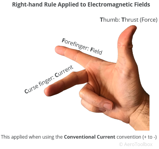
Flemming’s right-hand rule gives the direction of the current in the conventional sense (current flow from positive to negative). The current direction is reversed when considering the movement of the electrons which flow from the negative terminal to the positive terminal.
Alternating and Direct Current (AC & DC)
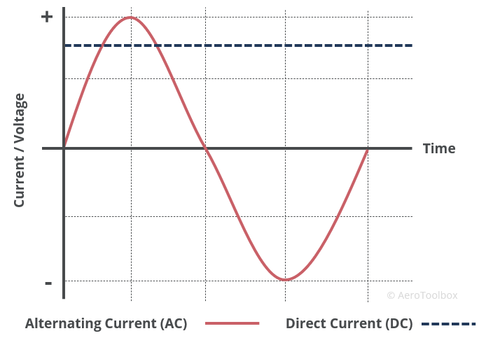
Electricity is delivered in one of two forms: alternating current or direct current.
- Direct Current (DC) is unidirectional. This means that the current only flows in one direction. A battery powering a flashlight is a good example of DC. The current and voltage from a DC power source are both unidirectional and constant.
- Alternating Current (AC) periodically reverses direction. The most common AC output is a sine wave. The electricity that powers your home and business is AC. AC is much easier and safer to distribute than DC as the voltage can be increased greatly through a transformer with a correspondingly large decease in current. The lower current reduces the energy lost due to resistance in the wire when being transported great distances.
An electrical generator can either output AC or DC depending on its design. The principle of electricity generation through electromagnetic induction is the same between the two, with a modification to the way the current leaves the armature that determines whether the resulting electricity is AC or DC.
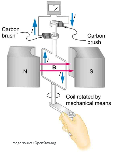
The AC Generator
The AC generator uses the rotation of the aircraft’s engine to spin multiple loops of conducting wire in a magnetic field. Alternating current is generated in the wire (armature) due to electromagnetic induction.
The workings of a generator are best described using a single loop of rotating wire as an example. This can then be extrapolated to multiple loops as is the case in a functional generator.
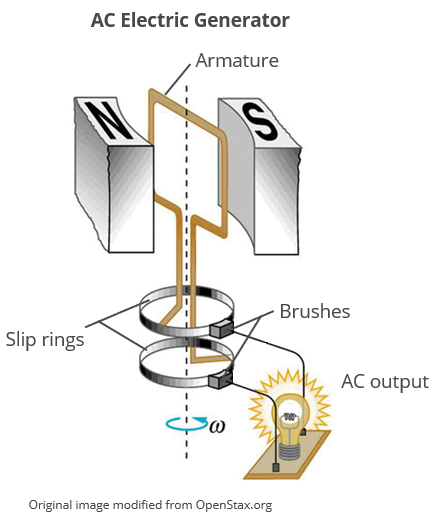
The armature is the moving portion of the generator and consists of loops of conducting wire arranged such that AC current will always be conducted through the wires due to electromagnetic induction.
The slip rings are located at the ends of the armature and feed the current induced in the armature into the broader electric circuit. Slip rings allow for easy transmission of the current generated from the rotating armature to the stationary circuit. There are two slip rings in an AC generator, one attached to each end of the armature. These slip rings rotate with the armature and slip past a set of brushes – transferring the current from the armature into the circuit.
The brushes are stationary but kept in constant contact with the slip rings in order to conduct and transmit the electricity generated by the armature.
Referring to the image below, we can see how the arrangement of the two slip rings and brushes result in an alternating current being fed into the circuit.
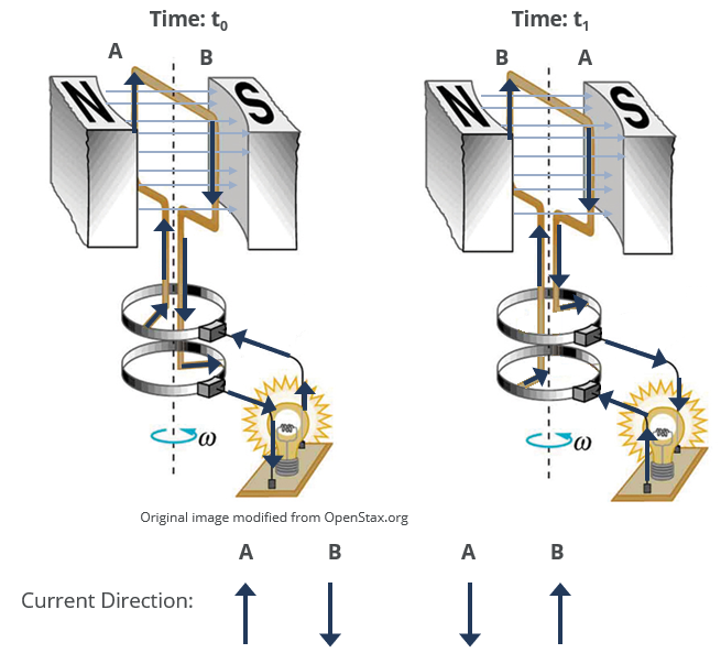
The two sides of the armature loop are labelled A and B.
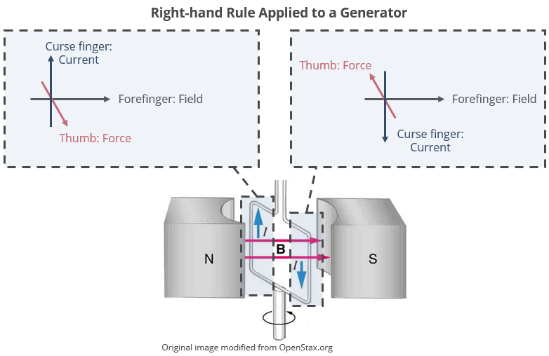
The armature is rotating in the magnetic field such that A is moving UPWARDS at time \(t_{0}\) and B is moving DOWNWARDS.
Using the right-hand rule, the directions of the current at \(t_{0}\) is up the page at A and down the page at B.
At a later time, \(t_{1}\), A and B have rotated through 180° such that A is now moving DOWNWARDS, and B is now moving UPWARDS.
Once again making use of the right-hand rule, we see that the current in A and B has now switched direction.
The direction of the current through the circuit is reversing every 180°. This is an alternating current output from the AC generator.
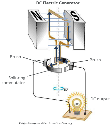
The DC Generator
An aircraft’s electrical system runs off DC and not AC. This is primarily due to the fact that the system must be powered by a battery when the engine is not operational. Batteries are DC by design.
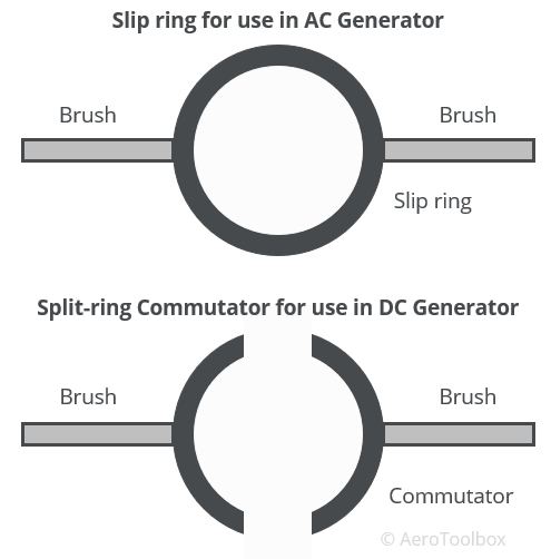
It is relatively easy to modify the AC generator described above to output a DC signal. This is accomplished by replacing the two slip rings with a split-ring commutator. Whereas the two ends of the armature are connected to separate slip rings in the AC generator setup, the DC setup uses a single ring which is split such that each half of the ring is completely isolated from the other. Each end of the armature loop is connected to one side of the single ring. The commutator then rotates as before, contacting the sides of the two brushes and passing the current into the circuit.
The split-ring ensures that each brush retains the same polarity throughout the operation of the generator.
The commutator provides a steady DC output that can be used to charge the battery or run any of the electronic systems in the aircraft.
An armature made from a single loop of conducting wire would not make a very effective generator as the magnetic flux lines are only crossed once every 180° as the conductor rotates. In reality, an armature is made up of many loops of wire such that the loops cross through the flux lines at a much greater frequency than would occur with only a single loop. This helps to provide a smooth and even electrical output to the circuit.
The AC Alternator
The AC alternator is a type of electrical generator that has largely replaced the DC generator described above in use in light aircraft (and automotive vehicles). The alternator serves the same purpose as a conventional generator, but is smaller, lighter, and requires less maintenance than the generators it replaced.
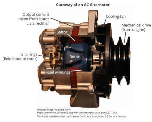
The alternator still works on the principle of electromagnetic induction where a changing magnetic field induces a current on the coil windings. The primary difference between an alternator and a conventional generator is that in an alternator the magnetic field is rotated by an engine-driven shaft (rotor), while the coil windings remain stationary (stator).
A cutaway of a typical alternator is shown below.
The rotor is connected to the mechanical drive shaft and consists of a centrally located electromagnet which is energised when the alternator is operating to provide the necessary magnetic field. The rotor forms the rotating portion of the alternator which spins inside the stationary stator ring. The stator contains a set of coil windings wound around the ring, into which current is induced as the rotor spins.

An alternating current is output by the stator coil windings, which is transformed into DC by a device called a rectifier. The rectifier uses a set of diodes, which can be thought of as the electrical equivalent of a one-way valve, to “straighten” out the alternating current into a DC signal that can be used to charge the aircraft battery or run the electrical system.
An alternator can provide a more consistent delivery of electricity over a wider range of operating speeds when compared to the DC generator. This is due to an automatic voltage control device fitted to the alternator which can regulate the current fed to the electromagnet, thereby increasing or decreasing the strength of the magnetic field. In cases where the engine rpm is low (idle or during taxi), the regulator increases the strength of the magnetic field to compensate for the lower rotor speed. When the engine is running at a higher power setting, the regulator reduces the voltage going to the electromagnet, which reduces the strength of the magnetic field. In this way a constant alternator output can be maintained over the full operating range of the aircraft’s engine.
The electromagnetic rotor is powered through the field circuit which connects the rotor to the aircraft’s DC battery through a set of slip rings and bushes. The aircraft’s battery is responsible for providing the voltage necessary to operate the electromagnet. This can be a problem if the battery is flat before the engine is started, as the alternator will not operate on a flat battery.
The bushes in the field circuit conduct only the current required to energize the electromagnet. This is a fraction of the current that is output by the alternator which dramatically reduces the wear on the bushes. In a conventional DC generator, the bushes must conduct the full generator output. These higher currents increase arching and wear on the bushes.
This brings us to the end of this tutorial. The final tutorial in this mini-series on the aircraft electrical system focuses on aircraft batteries. As always, if you enjoyed this post or found it useful as a study aid then please let your fellow student pilots know about AeroToolbox.com and share this on your favorite social media platform. Thanks again for reading.


