Lifting Surface Correction Factor
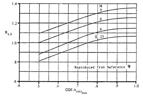
The calculation below provides an estimation of the lifting surface correction factor used when compiling an estimation of the zero lift drag produced by the wing. This is described in the tutorial on the Drag Polar. The graph shown below was originally published in USAF Stability and Control Datcom [1] and reproduced in Roskam Part VI Chapter 4.2 [2]. The calculator provides an estimation of the correction factor based on the digitization of the graph and an interpolation between datapoints. The methodology is described further below the calculator.

Calculation Methodology
The variation of \( R_{LS} \) with the cosine of the sweep angle at maximum thickness-to-chord ratio was digitally extracted from the graph (26 to 37 datapoints per Mach line). This formed the input into a linear interpolation using the sweep angle specified by the user. It is left to the user to determine whether the methodology employed is appropriately accurate.
[1] Hoak, D.E, et al, USAF Stability and Control Datcom, Flight Control Division, Air Force Flight Dynamics Laboratory, WPAFB, Ohio, 45433-0000, 1978, (approved for public release). Link to document.
[2] Roskam, J, Airplane Design Part VI: Preliminary Calculation of Aerodynamic, Thrust and Power Characteristics, Roskam Aviation and Engineering Corporation, 1987.
Popular Posts


