The image below of a cross-section through a typical wing, shows a number of fundamental definitions associated with airfoil (aerofoil) nomenclature.
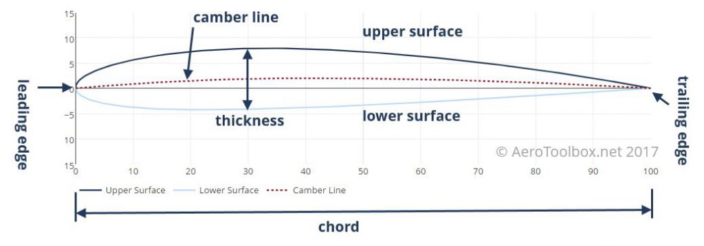
The forward section of the airfoil is named the leading edge and the rear the trailing edge. The airfoil upper and lower surfaces meet at the leading and trailing edges.
The length of the airfoil from leading to trailing edge is known as the airfoil chord. This often varies down the span of the wing as the wing tapers from the root to the tip.
The thickness of the airfoil is a very important design parameter and as always expressed as a percentage of the total chord. The airfoil plotted above has a thickness-to-chord ratio of 12%. This means that the thickest section has a height equal to 12% of the total chord.
The final design parameter camber is a measure of the asymmetry between the upper and lower surface. Camber is generally introduced to an airfoil to increase its maximum lift coefficient, which in turn decreases the stall speed of the aircraft. The camber line is a line drawn equidistant between the upper and lower surface at all points along the chord. Highly cambered airfoils produce more lift than lesser cambered airfoils, and an airfoil that has no camber is symmetrical upper and lower surface.
You can read further on airfoil aerodynamics in Part 4 of the Fundamentals of Aircraft Design Series.


