The landing gear, or undercarriage, has two primary requirements: (1) to support the aircraft while on the ground and (2) to absorb the large loads associated with landing, and transfer these from the wheels to the aircraft’s primary structure. This post will examine the various landing gear systems in operation, describe the components used to absorb the landing loads, and introduce some common gear retraction systems in use today.
Landing Gear Configurations
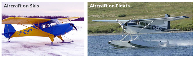
This post will focus on fixed-wing landing gear where it assumed that the aircraft will touch-down and land on a runway. Helicopters and other vertical take-off and landing vehicles may make use of skids rather than wheels to absorb the landing and to support the vehicle on the ground. Amphibious aircraft use floats or pontoons to land on bodies of water, and skis are used by light aircraft in snowy regions.
All landing gear configurations consist of a set of main wheels, designed to absorb the brunt of the landing load, and auxiliary wheels used to support the aircraft while on the ground. Whatever the configuration, the main wheels are larger, stronger, and located near the aircraft center of gravity (c.g.), while the auxiliary gear is located in such a position to allow the aircraft to remain balanced and supported on the ground.
Conventional Configuration (Tail wheel)
Early aircraft were designed with the main landing gear ahead of the center of gravity and a small nosewheel located at the tail. This is termed a conventional (or tailwheel) arrangement as this was the original configuration in popular use.
This configuration results in an aircraft with a nose high attitude on the ground, providing good propeller clearance and keeping the forward fuselage away from the landing surface.
A conventional gear arrangement is lighter than the more common tricycle arrangement as the tail wheel can be made small with a simple structure. Tail-wheel aircraft are considered more difficult to land than tricycle configurations, which is probably the reason for the decline in new aircraft fitted with a conventional layout.
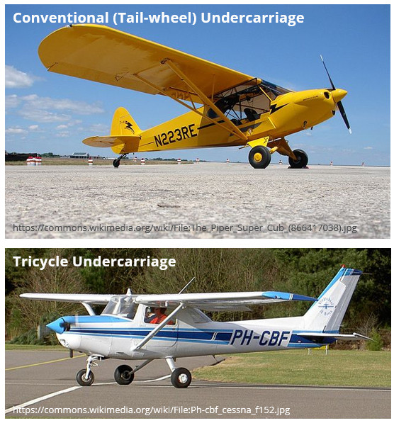
Tricycle Configuration
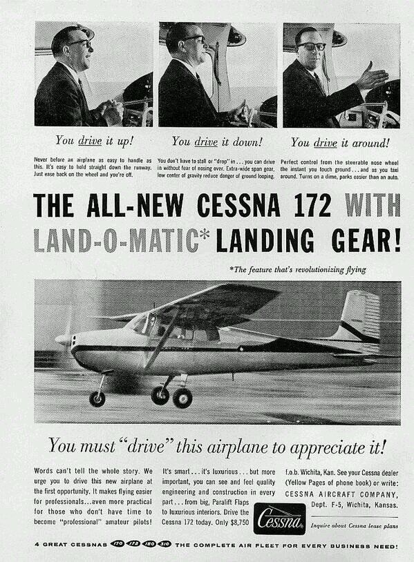
The more popular tricycle landing gear configuration primarily in use today gained popularity in the 1950’s and 1960’s in part due to Cessna’s “Land-O-Matic” promotional campaign which positioned tricycle aircraft as a very easy to land alternative to the conventional layout. The main gear sits just behind the center of gravity and a forward nosewheel completes the arrangement.
There are a number of advantages to using a tricycle arrangement in addition to it being easier to land due to improved visibility over the nose.
- Ground operations are easier as the nose of the aircraft is more-or-less level during taxi.
- Application of the brakes during landing will tend to push the nose down which is supported by the nosewheel. In a tail wheel aircraft, application of the brakes will cause the nose to tip down with no support. This can cause the aircraft to nose over if the brakes are applied too vigorously and at too high a speed.
- Ground loops are prevented with tricycle undercarriages as the center of gravity is ahead of the main landing gear.
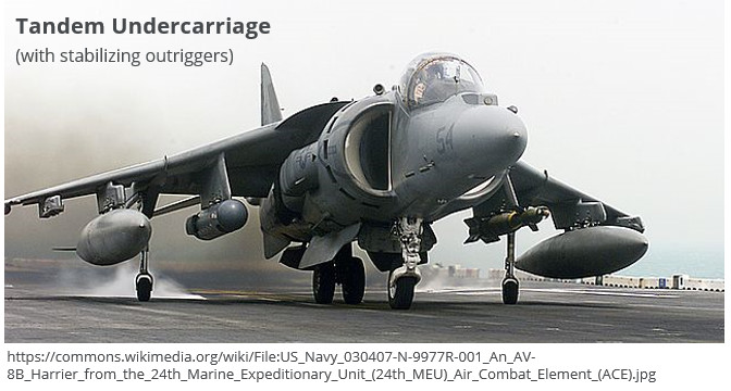
Tandem Configuration
Tandem arrangements are characterised by the main and auxiliary gear being aligned on the same longitudinal axis, usually with a number of smaller supporting outrigger gears to support the aircraft while on the ground. This configuration is not widely used as it presents difficulties in landing and ground operation. Some gliders use this configuration is it is very light – only a single main wheel is necessary on a small glider whereas conventional and tricycle undercarriages have at least three wheels.
The AV-8B Harrier II is an example of a tandem configuration aircraft. An outrigger installed on each wing provides the additional stabilization the aircraft requires once on the ground.
Fixed and Retractable Gear
Landing gear can be classified as either fixed or retractable. A fixed landing gear is far simpler and lighter to install on an aircraft as no heavy retraction mechanism is required. The airframe structure can also be made simpler and lighter as no cut-outs in either the fuselage or wing are required to house the wheels.
A fixed landing gear configuration is very common on small light aircraft, from basic trainers like a Cessna 172 to more performance orientated light aircraft such as the Cirrus SR-22.
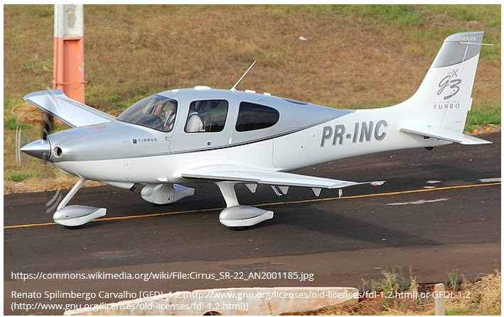
The largest disadvantage to a fixed gear arrangement is the additional parasite drag that the gear produces while the aircraft is in the cruise. Drag increases with the square of velocity and so as the speed is increased, so the drag increases exponentially. There is a speed above which the additional complexity and mass of a retractable undercarriage is outweighed by the performance advantage that a retractable gear can provide.
Fixed undercarriages can be made more aerodynamic through the use of streamlined struts and fairings to cover the wheels and landing gear legs. This can substantially reduce the parasite drag impact of the fixed gear – as is the case with the Cirrus SR-22.
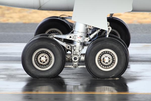
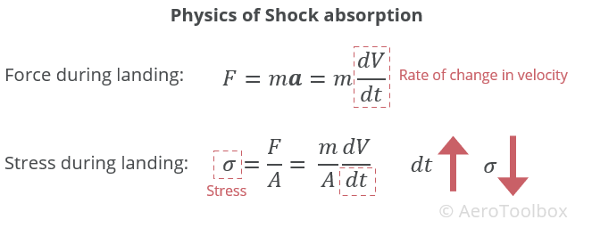
Shock Absorption
The action of landing involves an impact between the aircraft wheels and the runway that transfers a large amount of energy into the airframe. The magnitude of the forces and stresses transferred into the structure are a function of the rate of change of the impact velocity. The impact forces and stresses transferred to the airframe can be reduced by increasing the time over which the deceleration induced by the impact is transferred into the structure. This why almost all modern landing gear make use of some form of shock-absorption – either using a fixed spring steel (or composite) strut, or through the use of hydraulic shock struts.
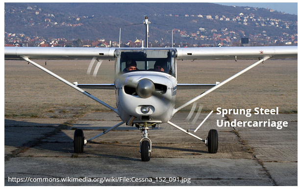
Leaf-Type Spring Strut
Many fixed wing aircraft (notably Cessna) make use of a cantilevered spring steel strut connecting the main wheels to the fuselage. The spring steel is able to flex and absorb the initial landing impact before transferring this into the fuselage, reducing the landing forces and stresses. The fixed strut does not have to be made from spring steel; composite landing gear are becoming more common – especially on many newer light sport aircraft.
Shock Struts
he higher landing speeds generally encountered on larger aircraft necessitate that shock-struts (shock absorbers) are used to dissipate the impact energy of landing. A shock strut works by converting the impact energy into heat through a rapid pressure increase in the strut cylinder during compression.
Design
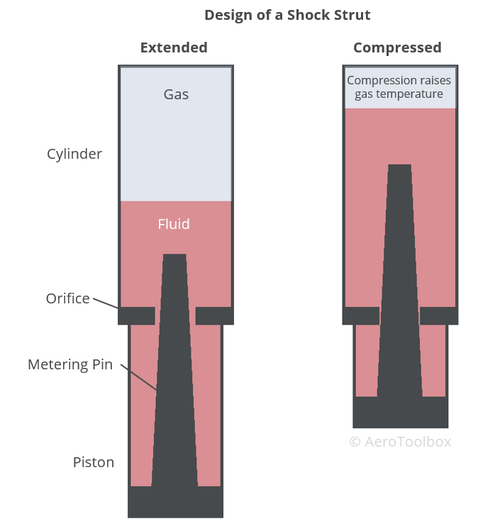
A typical shock strut consists of a cylinder and piston arrangement where a combination of hydraulic fluid and compressed air or nitrogen is used to absorb the shock. These struts are called air-oil or oleo struts and are commonly found on both main gear and nose landing gear. The upper portion of the strut contains the cylinder and is fixed to the aircraft structure. The lower portion contains the piston and is connected to the wheel. The piston is free to slide in and out of the cylinder as the load on the wheel changes. The cylinder is constructed from two chambers, the upper chamber is filled with compressed air or nitrogen, and the lower chamber is filled with hydraulic fluid. An orifice located between the two chambers allows fluid to penetrate into the upper cylinder under compression of the strut.
The rate at which the hydraulic fluid can enter the top chamber during compression is controlled by a metering pin. This is a tapered pin connected to the piston, which protrudes through the orifice. As the piston moves inwards and compression increases, the diameter of the pin passing through the orifice increases allowing less fluid through. This causes a large pressure build-up in the strut which raises the temperature of the gas. This dissipation of impact energy into heat lessens the energy transferred into the structure, damping the landing impact.
Torque Links
It is common for a shock strut to be fitted with a set of torque links or torque arms which prevents the piston from rotating inside the cylinder. The arms connect the upper cylinder with the lower piston, resisting any torque effects that may try to rotate the one inside the other. Torque arms keeps the wheel aligned which is necessary to affect a safe landing. The torque links are scissor shaped to allow the piston to extend and retract inside the main oleo cylinder.
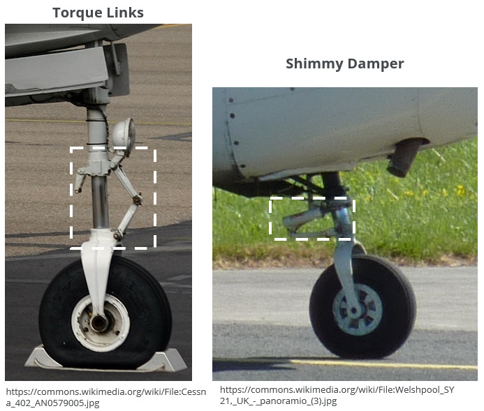
Shimmy Damper
The nosewheel on a tricycle undercarriage may tend to shimmy, which is a shaking or vibration felt by the pilot during the ground roll. An uncontrolled shimmy can cause a loss in directional control during take-off or landing. A worn oleo or loose torque links are often contributing factors to the development of a shimmy. A shimmy damper is installed on a nosewheel to damp out any vibration in the wheel. The shimmy damper consists of a small hydraulic piston and cylinder filled which is installed between the oleo cylinder and piston. A bleed hole between the damper cylinder and piston regulates the flow of hydraulic fluid during compression, damping out any shimmy effects.
Steering
Most light aircraft fitted with a nosewheel are steered via a mechanism that connects the nosewheel to the rudder pedals. Rudder inputs are transferred to the nosewheel by a mechanical push-rod system which rotates the wheel assembly around the oleo longitudinal axis.
Larger airliners make use of a hydraulic system to steer the nosewheel. Steering is not controlled by the rudder pedals but rather through a tiller which is a small wheel situated in the cockpit.
Gear Retraction
Once the cruise speed of an aircraft increases beyond a certain point, the additional drag caused by the landing gear in the slipstream necessitates that a gear retraction mechanism be installed on the aircraft to stow the gear after departure. Typical retraction mechanisms found on light aircraft are either actuated through an electric motor, or by a hydraulic power pack driven by an electrical pump.
Electrical Retraction
An all-electric mechanism is only really practical on a light aircraft where the mass of each landing gear leg is sufficiently low to be actuated by an electric motor. The motor’s rotational motion is geared and converted to a linear motion to actuate the landing gear up and down. The motor is reversible, allowing the pilot to raise and lower the gear as required.
Hydraulic Retraction
A hydraulic actuation system has the advantage that very large forces can be generated through hydraulic action, which is necessary to extend and retract the very heavy multi-wheeled landing gear bogies seen on larger aircraft. Airliners typically drive a set of hydraulic pumps off the main engines to actuate the gear.
Smaller aircraft make use of an electric/hydraulic power pack system to actuate the gear. The power pack is a small contained system that incorporates an electric pump to provide hydraulic pressure, a reservoir to house the hydraulic fluid, and a set of valves and hydraulic lines to transfer the fluid to and from a set of double-action actuators responsible for lowering and raising the gear.
Emergencies
All aircraft fitted with retractable undercarriage must provide the pilot a means to extend the gear in an emergency after failure of the nominal extension system. The means to deploy the gear in an emergency varies from manufacturer to manufacturer but may include a gravity driven extension system, or a manual mechanical system fitted in the cockpit. Compressed air is also used on some larger aircraft to extend the gear after a hydraulic failure.
The position of the landing gear is monitored by the pilot through an indication system installed in the cockpit. Typically, the state of the gear (nose and two main) is represented by a set of three lights in the cockpit. When the gear is down and locked in place, all lights are illuminated green. A gear in transit, either up or down, is colored yellow or red. If one of the gear legs does not completely lock in place during gear extension, then that light will remain amber or red to warn the pilot of a potential problem. A set of correctly stowed gear in flight is usually represented by no lights illuminated.